Multi-user chat using WebRTC. WebRTC technology: audio and video chat in the browser Connecting a new user
The purpose of this article is to use a demo sample of peer-to-peer video chat (p2p video chat) to familiarize yourself with its structure and operating principle. For this purpose, we will use the multi-user peer-to-peer video chat demo webrtc.io-demo. It can be downloaded from the link: https://github.com/webRTC/webrtc.io-demo/tree/master/site.
It should be noted that GitHub is a site or web service for the collaborative development of Web projects. On it, developers can post the codes of their developments, discuss them and communicate with each other. In addition, some large IT companies post their official repositories on this site. The service is free for open source projects. GitHub is a repository for open, free source code libraries.
So, we will place the demo sample of peer-to-peer video chat downloaded from GitHub on drive C personal computer in the created directory for our application "webrtc_demo".
Rice. 1
As follows from the structure (Fig. 1), peer-to-peer video chat consists of client script.js and server server.js scripts, implemented in the JavaScript programming language. Script (library) webrtc.io.js (CLIENT) - provides the organization of real-time communications between browsers using a peer-to-peer scheme: "client-client", and webrtc.io.js (CLIENT) and webrtc.io.js (SERVER), Using the WebSocket protocol, they provide duplex communication between the browser and the web server using a client-server architecture.
The webrtc.io.js (SERVER) script is included in the webrtc.io library and is located in the node_modules\webrtc.io\lib directory. The video chat interface index.html is implemented in HTML5 and CSS3. The contents of the webrtc_demo application files can be viewed using one of the html editors, for example "Notepad++".
We will check the working principle of video chat in file system PC. To run the server (server.js) on a PC, you need to install the node.js runtime environment. Node.js allows you to run JavaScript code outside of the browser. You can download node.js from the link: http://nodejs.org/ (version v0.10.13 as of 07/15/13). On the main page of the node.org website, click on the download button and go to http://nodejs.org/download/. For windows users first download win.installer (.msi), then run win.installer (.msi) on the PC, and install nodejs and "npm package manager" in the Program Files directory.

Rice. 2
Thus, node.js consists of an environment for developing and running JavaScript code, as well as a set of internal modules that can be installed using the manager or npm package manager.
To install modules you must command line From the application directory (for example, "webrtc_demo") run the command: npm install module_name. During the installation of modules, the npm manager creates a node_modules folder in the directory from which the installation was performed. During operation, nodejs automatically connects modules from the node_modules directory.
So, after installing node.js, open the command line and update the express module in the node_modules folder of the webrtc_demo directory using the npm package manager:
C:\webrtc_demo>npm install express
The express module is a web framework for node.js or a web platform for application development. To have global access to express, you can install it this way: npm install -g express.
Then update the webrtc.io module:
C:\webrtc_demo>npm install webrtc.io
Then on the command line we launch the server: server.js:
C:\webrtc_demo>node server.js

Rice. 3
That's it, the server is running successfully (Figure 3). Now, using a web browser, you can contact the server by IP address and load the index.html web page, from which the web browser will extract the client script code - script.js and the webrtc.io.js script code, and execute them. To operate peer-to-peer video chat (to establish a connection between two browsers), you need to contact the signal server running on node.js from two browsers that support webrtc.
As a result, the interface of the client part of the communication application (video chat) will open with a request for permission to access the camera and microphone (Fig. 4).

Rice. 4
After clicking the "Allow" button, the camera and microphone are connected for multimedia communication. In addition, you can communicate via text data through the video chat interface (Fig. 5).

Rice. 5
It should be noted that. The server is a signaling server, and is mainly designed to establish connections between user browsers. Node.js is used to operate the server.js server script that provides WebRTC signaling.
Today, WebRTC is the “hot” technology for streaming audio and video in browsers. Conservative technologies, such as HTTP Streaming and Flash, are more suitable for distributing recorded content (video on demand) and are significantly inferior to WebRTC in terms of real time and online broadcasts, i.e. where minimal video latency is required to allow viewers to see what is happening “live”.
The possibility of high-quality real-time communication comes from the WebRTC architecture itself, where the UDP protocol is used to transport video streams, which is the standard basis for transmitting video with minimal delays and is widely used in real-time communication systems.

Communication latency is important in online broadcasting systems, webinars and other applications that require interactive communication with the video source, end users and requires a solution.
Another good reason to try WebRTC is that it is definitely a trend. Today everyone Android Chrome the browser supports this technology, which guarantees millions of devices ready to watch the broadcast without installing any additional software or configurations.
In order to test WebRTC technology in action and launch a simple online broadcast on it, we used Flashphoner WebRTC Media & Broadcasting Server server software. The features state the ability to broadcast WebRTC streams in one-to-many mode, as well as support for IP cameras and video surveillance systems via the RTSP protocol; In this review we will focus on web-web broadcasts and their features.
Installing WebRTC Media & Broadcasting Server
Because for Windows systems there was no server version, and I didn’t want to install a virtual machine like VMWare+Linux, test online broadcasts on home Windows the computer did not work. To save time, we decided to take an instance on cloud hosting like this:

It was Centos x86_64 version 6.5 without any pre-installed software in the Amsterdam data center. Thus, all we have at our disposal is the server and ssh access to it. For those familiar with Linux console commands, installing WebRTC The server promises to be simple and painless. So what we did:
1. Download archive:
$wget https://site/download-wcs5-server.tar.gz
2. Unpack:
$tar -xzf download-wcs5-server.tar.gz
3. Install:
$cd FlashphonerWebCallServer
During installation, enter the server IP address: XXX.XXX.XXX.XXX
4. Activate license:
$cd /usr/local/FlashphonerWebCallServer/bin
$./activation.sh
5. Start WCS server:
$service webcallserver start
6. Check log:
$tail - f /usr/local/FlashphonerWebCallServer/logs/flashphoner_manager.log
7. Check that the two processes are in place:
$ps aux | grep Flashphoner
The installation process is complete.
Testing WebRTC online broadcasts
Testing the broadcasts turned out to be a simple matter. In addition to the server, there is a web client, which consists of a dozen Javascript, HTML and CSS files and was deployed by us to the /var/www/html folder during the installation stage. The only thing that had to be done was to enter the server’s IP address into the flashphoner.xml config so that the web client could establish a connection with the server via HTML5 Websockets. Let's describe the testing process.
1. Open the test client page index.html in Chrome browser e:

2.
In order to start broadcasting, you need to click the “Start” button in the middle of the screen.
Before you do this, you need to make sure that the webcam is connected and ready to use. There are no special requirements for the webcam; for example, we used a standard camera built into a laptop with a resolution of 1280x800.

The Chrome browser will definitely ask for access to the camera and microphone so that the user understands that his video will be sent to the Internet server and allows it.
3. The interface represents a successful broadcast of the video stream from the camera to the WebRTC server. In the upper right corner, an indicator indicates that the stream is going to the server; in the lower corner there is a “Stop” button to stop sending the video.

Please note the link in the box below. It contains a unique identifier for this stream, so anyone can join the viewing. Just open this link in your browser. To copy it to the clipboard, click on the “Copy” button.
In real applications such as webinars, lectures, online video broadcasts or interactive TV, developers will have to implement the distribution of this identifier to certain groups of viewers so that they can connect to the desired streams, but this is already the logic of the application. WebRTC Media & Broadcasting Server does not affect it, but only distributes videos.
5. The connection is established and the viewer sees the stream on the screen. Now he can send a link to someone else, stop the stream playing, or enable full-screen mode using the controls in the lower right corner.

Results of testing WebRTC online broadcast server
During tests, the latency seemed perfect. The ping to the data center was about 100 milliseconds and the delay was invisible to the eye. From here, we can assume that the real delay is the same 100 plus or minus a few tens of milliseconds for the buffering time. Compared to Flash video: in such tests, Flash does not behave as well as WebRTC. So, if you move your hand on a similar network, the movement on the screen can be seen only after one or two seconds.
Regarding quality, we note that cubes can sometimes be distinguished by movements. This is consistent with the nature of the VP8 codec and its main purpose - to provide real-time video communication with acceptable quality and without communication delays.
The server is quite easy to install and configure; running it does not require any serious skills other than knowledge of Linux at the level of an advanced user who can execute commands from the console via ssh and use text editor. As a result, we managed to set up a one-to-many online broadcast between browsers. Connecting additional viewers to the stream also did not pose any problems.
The broadcast quality turned out to be quite acceptable for webinars and online broadcasts. The only thing that raised some questions was the video resolution. The camera supports 1280x800, but the resolution in the test image is very similar to 640x480. Apparently, this issue needs to be clarified with the developers.
Video on testing broadcast from a webcam
via WebRTC server
European Internet users are divided into two parts: according to a survey by the Institute for Public Opinion Analysis in Allenbach (Germany), Skype, chat and instant messaging systems have become an integral part of everyday life for 16.5 million adults and children, 9 million use these services occasionally, and 28 million do not touch them.
This may change as Firefox now has integrated real-time communication technology (WebRTC), as well as the client himself. Starting an audio and video chat is now no more difficult than opening a website. Services such as Facebook and Skype, on the other hand, rely on solutions using a separate client and creating an account.
WebRTC is distinguished not only by its ease of use. This method even allows you to install direct connection between two browsers. This way, audio and video data does not pass through a server where there might be an overload or where the administrator is not particularly sensitive to privacy or data protection. Thanks to the direct connection, WebRTC requires neither registration nor account in any service.

To start a conversation, you only need to follow the link. Communication remains private, since the data stream is encrypted. Google began to actively engage in real-time communication through a browser back in 2011, when it published the source code of its WebRTC implementation.
Soon after this, Chrome and Firefox received their own WebRTC engines. Currently, their mobile versions are equipped with both this technology and the WebView 3.6 engine installed with Android 5.0, which is used by applications.
For real-time communication, appropriate JavaScript interfaces must be implemented in the web viewer. Using GetUserMedia software activates capture from audio and video sources, that is, from the webcam and microphone. RTCPeerConnection is responsible for establishing the connection as well as the communication itself.
In parallel with browser integration, a working group of the World Wide Web Consortium (W3C) accelerated the WebRTC standardization process. It should be completed in 2015.
WebRTC is content with little
Using the WebRTC service does not require many resources, since the server only connects the interlocutors. Establishing a connection is also not particularly difficult. First, the browser signals the WebRTC server that it plans to initiate a call. He receives an HTTPS link from the server - the communication is encrypted. The user sends this link to his interlocutor. The browser then asks the user for permission to access the webcam and microphone.
To establish a direct streaming connection with the interlocutor, the browser receives its IP address and configuration data from the WebRTC service. The other person's web viewer does the same.
In order for the streaming connection to function smoothly and in good quality, three engines work in the browser. Two of them optimize and compress audio and video data, the third is responsible for their transportation. It sends data via SRTP protocol(Secure Real-time Transport Protocol), which allows encrypted streaming in real time.
If a direct connection cannot be established, WebRTC looks for another path. For example, this happens when network settings prevent the STUN server from reporting the IP address. The WebRTC standard stipulates that in this case the conversation will take place, but with the intermediate activation of the TURN server (Traversal Using Relays around NAT). So, on the website netscan.co you can check whether WebRTC is implemented on your computer and with your access to the Network.
How the connection is made
 You must first register the conversation (1). The WebRTC service provides a link that must be sent to the interlocutor. The browser, using the STUN server, finds out its own IP address (2), sends it to the service and receives the partner’s IP to establish a direct connection (3). If STUN fails, the conversation is redirected using the TURN server (4).
Communication using WebRTC technology in the browser is launched using JavaScript code. After that, three engines are responsible for communication: the voice and video engines collect multimedia data from the webcam and microphone, and the transport engine combines the information and sends the stream in encrypted form using the SRTP (Secure Real-time Protocol).
Which browsers work with WebRTC
Chrome and Firefox have a WebRTC engine that uses services like talky.io. Mozilla's browser can work directly with its own client.

Google and Mozilla continue to develop the idea of real-time communication: Chrome can host WebRTC conferences with multiple participants, and Firefox's new Hello client was developed in collaboration with a subsidiary of telecom giant Telefonica. Apple is staying on the sidelines for now; you shouldn't expect WebRTC in Safari yet. However, there are many alternative iOS apps and Safari plugins.
Microsoft is taking a slightly different course. As the owner of the competing Skype service, this company is not going to capitulate so easily to WebRTC. Instead, Microsoft is developing a technology called ORTC (Object Real-Time Communications) for Internet Explorer.
Differences from WebRTC, such as different codecs and protocols for establishing contact with the server, are minor and over time will most likely develop into an addition to the WebRTC standard that includes these differences. Thus, only Apple is left behind - as usual.
Photo: manufacturing companies; goodluz/Fotolia.com
Hello friends, as you already know, we regularly update you with new technologies, today I will introduce WebRTC, a technology developed by by Google, which allows users to speak directly in the browser video and audio without requiring the use of plug-in websites or applications. Video and audio direct connection between users is carried out directly in the browser.
WebRTC technology is supported in Mozilla Firefox browsers Google Chrome and for any operating system, Opera will soon join.
What is WebRTC and what?
WebRTC is short for Web Real Time Communication, this technology allows you to open audio and video chats directly in the browser without the need for other plugins, applications or services on the Internet to do so. The connection is made directly from the browser in the browser.
If well-known services (Skype, Yahoo Messenger, Apple FaceTime, Google Hago, etc.) require a server that connects users to initiate and manage traffic. Using these services we need to register and set up a list of clients and contacts.
With WebRTC we don't need servers, applications or servers that connect to intercede.
WebRTC advantages:
1. No more apps consuming resources and battery.
2. Chats are more private (relatively speaking).
3. How to contact can be done locally, rather than Flos US servers for local connections.
4. Simplicity, ease of use.
5. Possibility of further development in other directions.
6. Communication is stable and does not depend on external connections, which are sometimes extremely unstable.
In the tutorial I used a demo that the people at Google developed, this demo is quite simple, more advanced features and more fast connections can use one of the applications that support WebRTC, they are easier to use. Soon we will be doing a tutorial about WebRTC applications as well.
How to use WebRTC demo?
Very simply click on the link below, it will automatically generate a chat. to link this room, you must send the boyfriend/girlfriend you want to get in touch with.
boyfriend/girlfriend and yours, but you should only use the most latest versions Mozilla Firefox or Google Chrome.
Demo WebRTC(Introductory chat audio - video)
Attention:
The demo is not very stable, produced for demonstration purposes only. It can be used for a limited period of time, during which small connection errors may occur.
If you have connection problems, try creating a different chat.
Most of the material on WebRTC focuses on the application level of coding and does not contribute to understanding the technology. Let's try to go deeper and find out how the connection occurs, what a session descriptor and candidates are, what are they needed for STUN And TURN server.
WebRTC
Introduction
WebRTC is a browser-oriented technology that allows you to connect two clients for video data transfer. Main features: internal browser support (no need for third-party implemented technologies like adobe flash ) and the ability to connect clients without using additional servers - connection peer-to-peer(further, p2p).
Establish a connection p2p- a rather difficult task, since computers do not always have public IP addresses, that is, addresses on the Internet. Due to the small quantity IPv4 addresses (and for security purposes), a mechanism was developed NAT, which allows you to create private networks, for example, for home use. Many home routers now support NAT and thanks to this, all home devices have access to the Internet, although Internet providers usually provide one IP address. Public IP addresses are unique on the Internet, but private addresses are not. Therefore connect p2p- difficult.
To understand this better, consider three situations: both nodes are on the same network (Figure 1), both nodes are on different networks (one is private, the other is public) (Figure 2) and both nodes are on different private networks with the same IP addresses (Figure 3).
Figure 1: Both nodes on the same network
 Figure 2: Nodes in different networks (one in private, one in public)
 Figure 3: Nodes in different private networks, but with numerically equal addresses
In the figures above, the first letter in the two-character notation indicates the type of node (p = peer, r = router). In the first figure, the situation is favorable: nodes in their network are fully identified by network IP addresses and can therefore connect to each other directly. In the second figure we have two different networks with similar node numbers. This is where routers (routers) appear, which have two network interfaces - inside their network and outside their network. That's why they have two IP addresses. Regular nodes have only one interface through which they can communicate only within their network. If they transmit data to someone outside their network, then only using NAT inside the router (router) and therefore visible to others under IP router address is theirs external IP address. Thus, at the node p1 There is interior IP = 192.168.0.200 And external IP = 10.50.200.5 , and the last address will also be external to all other nodes in its network. A similar situation for the node p2. Therefore, their connection is impossible if you use only their internal (own) IP addresses. You can use external addresses, that is, router addresses, but since all nodes in the same private network have the same external address, this is quite difficult. This problem is solved using the mechanism NAT
What will happen if we decide to connect nodes through their internal addresses? The data will not leave the network. To enhance the effect, you can imagine the situation shown in the last figure - both nodes have the same internal addresses. If they use them to communicate, then each node will communicate with itself.
WebRTC successfully copes with such problems using the protocol ICE, which, however, requires the use of additional servers ( STUN, TURN). More on all this below.
Two phases of WebRTC
To connect two nodes via a protocol WebRTC(or just RTC, if two communicate iPhone‘a) some preliminary steps must be taken to establish a connection. This is the first phase - establishing a connection. The second phase is video data transmission.
It’s worth saying right away that although technology WebRTC uses many different methods of communication in his work ( TCP And UDP) and has flexible switching between them, this technology does not have a protocol for transmitting connection data. Not surprising, because connect two nodes p2p not so easy. Therefore it is necessary to have some additional a method of data transmission that is in no way related to WebRTC. It could be a socket transfer, protocol HTTP, it could even be a protocol SMTP or Russian Post. This transmission mechanism initial data is called signal. Not much information needs to be conveyed. All data is transmitted in the form of text and is divided into two types - SDP And Ice Candidate. The first type is used to establish a logical connection, and the second for a physical connection. More on all this later, but for now it’s just important to remember that WebRTC will give us some information that will need to be transmitted to another node. As soon as we transfer all necessary information, the nodes will be able to connect and our help will no longer be needed. So the signaling mechanism we need to implement is separately, will be used only when connected, but will not be used when transmitting video data.
So, let's consider the first phase - the connection establishment phase. It consists of several points. Let's look at this phase first for the node that initiates the connection, and then for the one that is waiting.
- Initiator (caller - caller):
- Offer to start video data transfer (createOffer)
- Getting yours SDP SDP)
- Getting yours Ice candidate Ice candidate)
- Call waiting ( callee):
- Receiving a local (your) media stream and setting it for transmission (getUserMediaStream)
- Receiving an offer to start video data transfer and creating an answer (createAnswer)
- Getting yours SDP object and transmitting it through a signaling mechanism ( SDP)
- Getting yours Ice candidate objects and their transmission through a signaling mechanism ( Ice candidate)
- Receiving a remote (foreign) media stream and displaying it on the screen (onAddStream)
The only difference is in the second point.
Despite the apparent complexity of the steps, there are actually three of them: sending your own media stream (item 1), setting connection parameters (items 2-4), receiving someone else’s media stream (item 5). The most difficult step is the second step, because it consists of two parts: establishing physical And logical connections. The first indicates path, along which packets must travel to get from one network node to another. The second indicates video/audio parameters– what quality to use, what codecs to use.
Mental stage createOffer or createAnswer should be connected to transmission stages SDP And Ice candidate objects.
Basic Entities
Media streams (MediaStream)
The main entity is the media stream, that is, the stream of video and audio data, picture and sound. There are two types of media streams - local and remote. The local one receives data from input devices (camera, microphone), and the remote one via the network. Thus, each node has both a local and a remote thread. IN WebRTC there is an interface for threads MediaStream and there is also a subinterface LocalMediaStream specifically for local thread. IN JavaScript you can only encounter the first one, and if you use libjingle, then you may encounter the second one.
IN WebRTC There is a rather confusing hierarchy within the thread. Each stream can consist of several media tracks ( MediaTrack), which in turn can consist of several media channels ( MediaChannel). And there may also be several media streams themselves.
Let's look at everything in order. To do this, let's keep some example in mind. Let's say that we want to transmit not only a video of ourselves, but also a video of our table, on which lies a piece of paper on which we are going to write something. We will need two videos (us + table) and one audio (us). It is clear that we and the table should be divided into different threads, because this data is probably weakly dependent on each other. Therefore we will have two MediaStream‘a – one for us and one for the table. The first one will contain both video and audio data, and the second one will contain only video (Figure 4).
 Figure 4: Two different media streams. One for us, one for our table
It is immediately clear that a media stream at a minimum must include the ability to contain data different types- video and audio. This is taken into account in the technology and therefore each type of data is implemented through a media track MediaTrack. Media tracks have a special property kind, which determines what we have in front of us – video or audio (Figure 5)
 Figure 5: Media streams consist of media tracks
How will everything happen in the program? We will create two media streams. Then we will create two video tracks and one audio track. Let's get access to the cameras and microphone. Let's tell each track which device to use. Let's add a video and audio track to the first media stream and a video track from another camera to the second media stream.
But how do we distinguish media streams at the other end of the connection? To do this, each media stream has the property label– stream label, its name (Figure 6). Media tracks have the same property. Although at first glance it seems that video can be distinguished from sound in other ways.
 Figure 6: Media streams and tracks are identified by labels
So, if media tracks can be identified through a tag, then why do we need to use two media streams for our example, instead of one? After all, you can transmit one media stream, but use different tracks in it. We have reached an important property of media streams - they synchronize media tracks. Different media streams are not synchronized with each other, but within each media stream all tracks are played simultaneously.
Thus, if we want our words, our facial emotions and our piece of paper to be played simultaneously, then it is worth using one media stream. If this is not so important, then it is more profitable to use different streams - the picture will be smoother.
If some track needs to be turned off during transmission, you can use the property enabled media tracks.
Finally, it's worth thinking about stereo sound. As you know, stereo sound is two different sounds. And they must also be transferred separately. Channels are used for this MediaChannel. A media audio track can have many channels (for example, 6 if you need 5+1 audio). There are also channels inside the media tracks, of course. synchronized. For video, usually only one channel is used, but several can be used, for example, for overlaying advertising.
To summarize: We use a media stream to transmit video and audio data. Within each media stream, the data is synchronized. We can use multiple media streams if we don't need synchronization. Inside each media stream there are two types of media tracks - for video and for audio. There are usually no more than two tracks, but there may be more if you need to transmit several different videos (of the interlocutor and his table). Each track can consist of several channels, which is usually used only for stereo sound.
In the simplest video chat situation, we will have one local media stream, which will consist of two tracks - a video track and an audio track, each of which will consist of one main channel. The video track is responsible for the camera, the audio track is for the microphone, and the media stream is the container for both of them.
Session Descriptor (SDP)
Different computers will always have different cameras, microphones, video cards and other equipment. There are many options they have. All this must be coordinated for media transfer of data between two network nodes. WebRTC does this automatically and creates a special object - a session descriptor SDP. Pass this object to another node, and media data can be transferred. Only there is no connection with another node yet.
Any signaling mechanism is used for this. SDP can be transmitted either through sockets, or by person (tell it to another node by phone), or by Russian Post. It’s very simple - they will give you a ready-made SDP and it needs to be sent. And upon receipt on the other side - transfer to the department WebRTC. The session descriptor is stored as text and can be changed in your applications, but this is generally not necessary. As an example, when connecting desktop ↔ phone, sometimes you need to force the selection of the desired audio codec.
Usually, when establishing a connection, you need to specify some kind of address, for example URL. This is not necessary here, since through the signaling mechanism you yourself will send the data to its destination. To indicate WebRTC what we want to install p2p connection you need to call the createOffer function. After calling this function and giving it a special callback‘a will be created SDP object and transferred to the same callback. All that is required of you is to transfer this object over the network to another node (interlocutor). After this, data will arrive at the other end through the signaling mechanism, namely this SDP object. This session descriptor for this node is foreign and therefore carries useful information. Receiving this object is a signal to start the connection. Therefore, you must agree to this and call the createAnswer function. It is a complete analogue of createOffer. Back to yours callback will pass the local session descriptor and it will need to be passed back via the signaling mechanism.
It is worth noting that you can call the createAnswer function only after receiving someone else's SDP object. Why? Because local SDP the object that will be generated when createAnswer is called must rely on the remote SDP object. Only in this case is it possible to coordinate your video settings with the settings of your interlocutor. Also, you should not call createAnswer and createOffer before receiving the local media stream - they will have nothing to write to SDP object .
Since in WebRTC it is possible to edit SDP object, then after receiving the local handle it must be installed. This may seem a little strange to convey WebRTC what she herself gave us, but that’s the protocol. When a remote handle is received, it must also be installed. Therefore, you must install two descriptors on one node - yours and someone else's (that is, local and remote).
After this handshakes nodes know about each other's wishes. For example, if the node 1 supports codecs A And B, and the node 2 supports codecs B And C, then, since each node knows its own and others’ descriptors, both nodes will choose the codec B(Figure 7). The connection logic is now established and media streams can be transmitted, but there is another problem - the nodes are still connected only by a signaling mechanism.
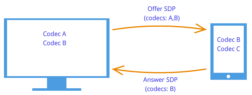
 Figure 7: Codec negotiation
Ice candidate
Technology WebRTC trying to confuse us with his new methodology. When establishing a connection, the address of the node to which you want to connect is not specified. Installed first logical connection, not physical, although the opposite was always done. But this will not seem strange if we do not forget that we are using a third-party signaling mechanism.
So, the connection has already been established (logical connection), but there is still no path along which the network nodes can transmit data. It's not all that simple, but let's start simple. Let the nodes be on the same private network. As we already know, they can easily connect with each other according to their internal IP addresses (or perhaps to some other, if not used TCP/IP).
After some callback'And WebRTC tells us Ice candidate objects. They also come in text form and, like session descriptors, they simply need to be sent through a signaling mechanism. If the session descriptor contained information about our settings at the camera and microphone level, then the candidates contain information about our location on the network. Pass them on to another node, and it will be able to physically connect to us, and since it already has a session descriptor, it will logically be able to connect and the data will “flow.” If he remembers to send us his candidate object, that is, information about where he himself is on the network, then we will be able to connect with him. Let us note here one more difference from the classic client-server interaction. Communication with the HTTP server occurs according to the request-response scheme, the client sends data to the server, which processes it and sends it via the address specified in the request packet. IN WebRTC need to know two addresses and connect them on both sides.
The difference from session descriptors is that only remote candidates need to be installed. Editing here is prohibited and cannot bring any benefit. In some implementations WebRTC candidates need to be installed only after session descriptors have been set.
Why was there only one session descriptor, but there could be many candidates? Because the location on the network can be determined not only by its internal IP address, but also the external address of the router, and not necessarily just one, as well as the addresses TURN servers. The rest of the paragraph will be devoted to a detailed discussion of the candidates and how to connect nodes from different private networks.
So, two nodes are on the same network (Figure 8). How to identify them? By using IP addresses. No more. True, you can still use different transports ( TCP And UDP) and different ports. This is the information contained in the candidate object - IP, PORT, TRANSPORT and some other one. Let, for example, use UDP transport and 531 port.
Figure 8: Two nodes are on the same network
Then if we are at the node p1, That WebRTC will pass us such a candidate object - . This is not an exact format, just a diagram. If we are in a knot p2, then the candidate is – . Through a signaling mechanism p1 will receive a candidate p2(i.e. node location p2, namely his IP And PORT). After which p1 can connect with p2 directly. More correctly, p1 will send data to the address 10.50.150.3:531 in the hope that they will reach p2. It doesn't matter if the address belongs to the node p2 or some intermediary. The only important thing is that data will be sent through this address and can reach p2.
As long as nodes are on the same network, everything is simple and easy - each node has only one candidate object (always meaning its own, that is, its location in the network). But there will be many more candidates when the nodes are in different networks.
Let's move on to a more complex case. One node will be located behind the router (more precisely, behind NAT), and the second node will be located on the same network with this router (for example, on the Internet) (Figure 9).
Figure 9: One node is behind NAT, the other is not
This case has a particular solution to the problem, which we will now consider. A home router usually contains a table NAT. This is a special mechanism designed to allow nodes inside the router’s private network to access, for example, websites.
Let's assume that the web server is connected to the Internet directly, that is, it has a public IP* address. Let this be a node p2. Knot p1(web client) sends a request to the address 10.50.200.10 . First the data goes to the router r1, or rather on his interior interface 192.168.0.1 . After which, the router remembers the source address (address p1) and enters it into a special table NAT, then changes the source address to yours( p1 → r1). Further, in my own way external interface, the router sends data directly to the web server p2. The web server processes the data, generates a response and sends it back. Sends to router r1, since it is he who is in the return address (the router replaced the address with its own). The router receives data and looks at the table NAT and forwards the data to the node p1. The router acts as an intermediary here.
What if several nodes from the internal network simultaneously access the external network? How will the router understand who to send the response back to? This problem is solved using ports. When a router replaces the host address with its own, it also replaces the port. If two nodes access the Internet, then the router replaces their source ports with different. Then, when the packet from the web server comes back to the router, the router will understand by the port who the packet is assigned to. Example below.
Let's return to technology WebRTC, or rather, to the part of it that uses ICE protocol (hence Ice candidates). Knot p2 has one candidate (its location in the network – 10.50.200.10 ), and the node p1, which is located behind a router with NAT, will have two candidates - local ( 192.168.0.200 ) and router candidate ( 10.50.200.5 ). The first one is not useful, but it is generated nonetheless, since WebRTC does not yet know anything about the remote node - it may or may not be on the same network. The second candidate will come in handy, and as we already know, the port will play an important role (to pass through NAT).
Table entry NAT generated only when data leaves the internal network. Therefore the node p1 must transmit the data first and only after that the node data p2 will be able to reach the node p1.
In practice both nodes will be behind NAT. To create a record in a table NAT of each router, the nodes must send something to the remote node, but this time neither the first one can reach the second one, nor vice versa. This is due to the fact that nodes do not know their external IP addresses, and sending data to internal addresses is pointless.
However, if the external addresses are known, the connection will be easily established. If the first node sends data to the router of the second node, the router will ignore it, since its table NAT empty for now. However, in the router of the first node in the table NAT I need a recording. If now the second node sends data to the router of the first node, then the router will successfully transfer it to the first node. Now the table NAT the second router needs data.
The problem is that in order to recognize your external IP address, you need a node located in shared network. To solve this problem, additional servers are used that are directly connected to the Internet. With their help, treasured entries in the table are also created NAT.
STUN and TURN servers
On initialization WebRTC you must indicate the available STUN And TURN servers, which we will further call ICE servers. If servers are not specified, then only nodes in the same network (connected to it without NAT). It is immediately worth noting that for 3g-networks must be used TURN servers.
STUN server is simply a server on the Internet that returns a return address, that is, the address of the sender’s node. The node located behind the router accesses STUN server to go through NAT. The package arrived at STUN server, contains the source address - the address of the router, that is, the external address of our node. This address STUN server and sends it back. Thus, the node receives its external IP the address and port through which it is accessible from the network. Next, WebRTC using this address creates an additional candidate (external router address and port). Now in the table NAT The router has an entry that allows packets sent to the router on the required port to pass through to our node.
Let's look at this process with an example.
Example (STUN server operation)
STUN we will denote the server by s1. The router, as before, through r1, and the node – through p1. You will also need to follow the table NAT– let’s denote it as r1_nat. Moreover, this table usually contains many records from different nodes of the subnet - they will not be given.
So, at the beginning we have an empty table r1_nat.
Table 2: Packet Header
Knot p1 sends this packet to the router r1(no matter how, they can be used in different subnets different technologies). The router needs to change the source address Src IP, since the address specified in the packet is obviously not suitable for an external subnet; moreover, addresses from such a range are reserved, and not a single address on the Internet has such an address. The router makes a substitution in the packet and creates new entry in your table r1_nat. To do this, he needs to come up with a port number. Let us recall that since several nodes within a subnet can access the external network, then in the table NAT must be kept additional information, so that the router can determine which of these several nodes is destined for the return packet from the server. Let the router come up with a port 888 .
Changed package header:
Table 4: The NAT table has been updated with a new entry
Here IP the address and port for the subnet are exactly the same as the original packet. In fact, when postbacking, we must have a way to completely restore them. IP the address for the external network is the address of the router, and the port has changed to the one invented by the router.
The real port to which the node p1 accepts the connection - this, of course, 35777 , but the server sends data to fictitious port 888 , which will be changed by the router to the real one 35777 .
So, the router replaced the source address and port in the packet header and added an entry to the table NAT. Now the packet is sent over the network to the server, that is, the node s1. At the entrance, s1 has this package:
| Src IP | Src PORT | Dest IP | Dest PORT |
|---|---|---|---|
| 10.50.200.5 | 888 | 12.62.100.200 | 6000 |
Table 5: STUN server received packet
Total STUN the server knows that it received a packet from the address 10.50.200.5:888 . Now the server sends this address back. It's worth stopping here and taking another look at what we just looked at. The tables above are a snippet from header package, not at all from it content. We did not talk about the contents, since it is not so important - it is somehow described in the protocol STUN. Now we will consider, in addition to the title, the content. It will be simple and contain the router address - 10.50.200.5:888 , although we took it from header package. This is not done often, usually the protocols do not care about information about node addresses, it is only important that the packets are delivered to their intended destination. Here we are looking at a protocol that establishes a path between two nodes.
So now we have a second packet that goes in the opposite direction:
Table 7: STUN server sends a packet with this content
Next, the packet travels across the network until it reaches the external interface of the router r1. The router understands that the packet is not intended for it. How does he understand this? This can only be determined by the port. Port 888 he does not use it for his personal purposes, but uses it for the mechanism NAT. Therefore, the router looks at this table. Looks at the column External PORT and looks for a string that matches Dest PORT from the incoming package, that is 888 .
| Internal IP | Internal PORT | External IP | External PORT |
|---|---|---|---|
| 192.168.0.200 | 35777 | 10.50.200.5 | 888 |
Table 8: NAT Table
We're lucky, such a line exists. If we were unlucky, the packet would simply be discarded. Now you need to understand which node on the subnet should send this packet. No need to rush, let's again remember the importance of ports in this mechanism. At the same time, two nodes on the subnet could send requests to the external network. Then, if for the first node the router came up with a port 888 , then for the second he would come up with a port 889 . Let's assume that this happened, that is, the table r1_nat looks like this:
Table 10: The router replaces the receiver address
| Src IP | Src PORT | Dest IP | Dest PORT |
|---|---|---|---|
| 12.62.100.200 | 6000 | 192.168.0.200 | 35777 |
Table 11: The router changed the receiver address
The packet arrives successfully at the node p1 and by looking at the contents of the packet, the node learns about its external IP address, that is, the address of the router on the external network. He also knows the port that the router passes through NAT.
What's next? What's the use of all this? Benefit is an entry in the table r1_nat. If now anyone sends to the router r1 package with port 888 , then the router will forward this packet to the node p1. Thus, a small narrow passage was created to the hidden node p1.
From the example above you can get some idea of how it works NAT and essence STUN server. In general, the mechanism ICE And STUN/TURN servers are precisely aimed at overcoming limitations NAT.
Between the node and the server there can be not one router, but several. In this case, the node will receive the address of the router that is the first to access the same network as the server. In other words, we get the address of the router connected to STUN server. For p2p communication is exactly what we need, if we don’t forget the fact that each router will add the row we need to the table NAT. Therefore, the way back will be just as smooth again.
TURN the server is improved STUN server. From here it should immediately be learned that any TURN the server can work and how STUN server. However, there are also advantages. If p2p communication is impossible (such as in 3g networks), then the server switches to repeater mode ( relay), that is, it works as an intermediary. Of course, about nothing p2p then there is no question, but outside the framework of the mechanism ICE the nodes think they are communicating directly.
In what cases is it necessary TURN server? Why is there not enough STUN servers? The fact is that there are several varieties NAT. They substitute equally IP address and port, but some of them have built-in additional protection from “falsification”. For example, in symmetrical table NAT 2 more parameters are saved - IP and the port of the remote node. A packet from the external network passes through NAT to the internal network only if the source address and port match those recorded in the table. Therefore, the focus STUN server fails - table NAT stores address and port STUN server and when the router receives a packet from WebRTC interlocutor, he discards it because it is “falsified.” He didn't come from STUN server.
Thus TURN a server is needed when both interlocutors are located symmetrical NAT(each to his own).
Brief summary
Here are some statements about entities WebRTC which must always be kept in mind. They are described in detail above. If any of the statements do not seem completely clear to you, re-read the relevant paragraphs.
- Media stream
- Video and audio data are packaged into media streams
- Media streams synchronize the media tracks that make up
- Different media streams are not synchronized with each other
- Media streams can be local and remote, the local one is usually connected to a camera and microphone, the remote ones receive data from the network in encrypted form
- There are two types of media tracks - for video and for audio.
- Media tracks have the ability to turn on/off
- Media tracks consist of media channels
- Media tracks synchronize the media channels that make up
- Media streams and media tracks have labels by which they can be distinguished
- Session handle
- The session descriptor is used to logically connect two network nodes
- The session descriptor stores information about available ways encoding video and audio data
- WebRTC uses an external signaling mechanism - the task of forwarding session descriptors ( sdp) falls on the application
- The logical connection mechanism consists of two stages - sentences ( offer) and answer ( answer)
- Generation of a session descriptor is not possible without using a local media stream in the case of a proposal ( offer) and is not possible without using a remote session handle in case of a response ( answer)
- The resulting descriptor must be given to the implementation WebRTC, and it does not matter whether this descriptor is obtained remotely or locally from the same implementation WebRTC
- It is possible to slightly edit the session descriptor
- Candidates
- Candidate ( Ice candidate) is the address of the node on the network
- The node address can be your own, or it can be the address of a router or TURN servers
- There are always many candidates
- The candidate consists of IP address, port and type of transport ( TCP or UDP)
- Candidates are used to establish a physical connection between two nodes in a network
- Candidates also need to be sent through a signaling mechanism
- Candidates also need to be transferred to implementations WebRTC, however only remote
- In some implementations WebRTC candidates can only be transmitted after the session descriptor has been set
- STUN/TURN/ICE/NAT
- NAT– mechanism for providing access to the external network
- Home routers support a special table NAT
- The router replaces the addresses in the packets - the source address with its own, if the packet goes to an external network, and the receiver address with the host address on the internal network, if the packet came from an external network
- To provide multi-channel access to the external network NAT uses ports
- ICE– bypass mechanism NAT
- STUN And TURN servers – helper servers for bypassing NAT
- STUN the server allows you to create the necessary records in the table NAT, and also returns the external address of the node
- TURN server generalizes STUN mechanism and makes it always work
- In the worst cases TURN the server is used as an intermediary ( relay), that is p2p turns into a client-server-client communication.


