DIY dimmer circuits. Homemade two-stage temperature controller
Many soldering irons are sold without a power regulator. When turned on, the temperature rises to maximum and remains in this state. To adjust it, you need to disconnect the device from the power source. In such soldering irons, the flux instantly evaporates, oxides are formed and the tip is in a constantly contaminated state. It has to be cleaned frequently. Soldering large components requires high temperatures, but small parts can be burned. To avoid such problems, power regulators are made.
How to make a reliable power regulator for a soldering iron with your own hands
Power controls help control the heat level of the soldering iron.
Connecting a ready-made heating power controller
If you do not have the opportunity or desire to tinker with the manufacture of the board and electronic components, then you can buy a ready-made power regulator at a radio store or order it online. The regulator is also called a dimmer. Depending on the power, the device costs 100–200 rubles. You may need to modify it a little after purchase. Dimmers up to 1000 W are usually sold without a cooling radiator.
Power regulator without radiator
And devices from 1000 to 2000 W with a small radiator.
Power regulator with small heatsink
And only the more powerful ones are sold with large radiators. But in fact, a dimmer from 500 W should have a small cooling radiator, and from 1500 W large aluminum plates are already installed.
Chinese power regulator with large radiator
Please take this into account when connecting the device. If necessary, install a powerful cooling radiator.
Modified power regulator
For correct connection devices to the circuit, look at the back of the printed circuit board. The IN and OUT terminals are indicated there. The input is connected to a power outlet, and the output to a soldering iron.
Designation of input and output terminals on the board
The regulator is installed in different ways. To implement them, you do not need special knowledge, and the only tools you need are a knife, a drill and a screwdriver. For example, you can include a dimmer in the power cord of a soldering iron. This is the easiest option.
- Cut the soldering iron cable into two parts.
- Connect both wires to the board terminals. Screw the section with the fork to the entrance.
- Select a plastic case of suitable size, make two holes in it and install the regulator there.
Another simple way: you can install the regulator and socket on a wooden stand.
You can connect not only a soldering iron to such a regulator. Now let's look at a more complex, but compact option.
- Take a large plug from an unnecessary power supply.
- Remove the existing board with electronic components from it.
- Drill holes for the dimmer handle and two terminals for the input plug. The terminals are sold at a radio store.
- If your regulator has indicator lights, make holes for them too.
- Install the dimmer and terminals into the plug body.
- Take a portable socket and plug it in. Insert the plug with the regulator into it.
This device, like the previous one, allows you to connect different devices.
Homemade two-stage temperature controller
The simplest power regulator is a two-stage one. It allows you to switch between two values: maximum and half of maximum.
Two-stage power regulator
When the circuit is open, current flows through diode VD1. Output voltage 110 V. When the circuit is closed with switch S1, the current bypasses the diode, since it is connected in parallel and the output voltage is 220 V. Select the diode in accordance with the power of your soldering iron. The output power of the regulator is calculated by the formula: P = I * 220, where I is the diode current. For example, for a diode with a current of 0.3 A, the power is calculated as follows: 0.3 * 220 = 66 W.
Since our block consists of only two elements, it can be placed in the body of the soldering iron using hinged mounting.
- Solder parallel parts of the microcircuit to each other directly using the legs of the elements themselves and the wires.
- Connect to the chain.
- Fill everything with epoxy resin, which serves as an insulator and protection against movement.
- Make a hole in the handle for the button.
If the housing is very small, use a light switch. Mount it into the soldering iron cord and insert a diode parallel to the switch.
Switch for lamp
On a triac (with indicator)
Let's consider simple diagram regulator on a triac and we will make a printed circuit board for it.
Triac power regulator
PCB manufacturing
Since the circuit is very simple, there is no point in installing it alone computer program for processing electrical circuits. Moreover, special paper is needed for printing. And not everyone has laser printer. Therefore, we will take the simplest route of manufacturing a printed circuit board.
- Take a piece of PCB. Cut to the size required for the chip. Sand the surface and degrease.
- Take a marker for laser discs and draw a diagram on the PCB. To avoid mistakes, draw with a pencil first.
- Next, we start etching. You can buy ferric chloride, but the sink is difficult to clean after it. If you accidentally drop it on your clothes, it will leave stains that cannot be completely removed. Therefore, we will use a safe and cheap method. Prepare a plastic container for the solution. Pour in 100 ml hydrogen peroxide. Add half a tablespoon of salt and a packet of citric acid up to 50 g. The solution is made without water. You can experiment with proportions. And always make a fresh solution. All copper should be removed. This takes about an hour.
- Rinse the board under running water. Dry. Drill the holes.
- Wipe the board with alcohol-rosin flux or a regular solution of rosin in isopropyl alcohol. Take some solder and tin the tracks.
To apply the diagram on PCB, you can make it even easier. Draw a diagram on paper. Glue it with tape to the cut out PCB and drill holes. And only after that draw the circuit with a marker on the board and etch it.
Installation
Prepare all necessary components for installation:
- solder spool;
- pins into the board;
- triac bta16;
- 100 nF capacitor;
- 2 kOhm fixed resistor;
- dinistor db3;
- variable resistor with a linear dependence of 500 kOhm.
Proceed to install the board.
- Cut off four pins and solder them onto the board.
- Install the dinistor and all other parts except the variable resistor. Solder the triac last.
- Take a needle and brush. Clean the gaps between the tracks to remove any possible shorts.
- Take an aluminum radiator to cool the triac. Drill a hole in it. The triac with its free end with a hole will be attached to an aluminum radiator for cooling.
- Use fine sandpaper to clean the area where the element is attached. Take heat-conducting paste of the KPT-8 brand and apply a small amount of paste to the radiator.
- Secure the triac with a screw and nut.
- Carefully bend the board so that the triac takes a vertical position in relation to it. To make the design compact.
- Since all parts of our device are under mains voltage, we will use a handle made of insulating material for adjustment. This is very important. Using metal holders here is dangerous to life. Place the plastic handle on the variable resistor.
- Use a piece of wire to connect the outer and middle terminals of the resistor.
- Now solder two wires to the outer terminals. Connect the opposite ends of the wires to the corresponding pins on the board.
- Take the socket. Remove the top cover. Connect the two wires.
- Solder one wire from the socket to the board.
- And connect the second one to the two-wire wire network cable with a fork. The power cord has one free core left. Solder it to the corresponding contact on the printed circuit board.
In fact, it turns out that the regulator is connected in series to the load power circuit.
Connection diagram of the regulator to the circuit
If you want to install an LED indicator in the power regulator, then use a different circuit.
Power regulator circuit with LED indicator
Diodes added here:
- VD 1 - diode 1N4148;
- VD 2 - LED (operation indication).
The triac circuit is too bulky to be included in a soldering iron handle, as is the case with a two-stage regulator, so it must be connected externally.
Installation of the structure in a separate housing
All elements of this device are under mains voltage, so a metal case cannot be used.
- Take a plastic box. Outline how the board with the radiator will be placed in it and which side to connect the power cord from. Drill three holes. The two extreme ones are needed to attach the socket, and the middle one is for the radiator. The head of the screw to which the radiator will be attached must be hidden under the socket for electrical safety reasons. The radiator has contact with the circuit, and it has direct contact with the network.
- Make another hole on the side of the case for the network cable.
- Install the radiator mounting screw. Place the washer on the back side. Screw on the radiator.
- Drill a hole of the appropriate size for the potentiometer, that is, for the handle of the variable resistor. Insert the part into the body and secure with a standard nut.
- Place the socket on the body and drill two holes for the wires.
- Secure the socket with two M3 nuts. Insert the wires into the holes and tighten the cover with a screw.
- Route the wires inside the housing. Solder one of them to the board.
- The other is for the core of the network cable, which you first insert into the plastic housing of the regulator.
- Insulate the joint with electrical tape.
- Connect the free wire of the cord to the board.
- Close the housing with the lid and tighten it with screws.
The power regulator is plugged into the network, and the soldering iron is plugged into the regulator socket.
Video: installation of the regulator circuit on a triac and assembly in the housing
On a thyristor
The power regulator can be made using a bt169d thyristor.
Thyristor power regulator
Circuit components:
- VS1 - thyristor BT169D;
- VD1 - diode 1N4007;
- R1 - 220k resistor;
- R3 - 1k resistor;
- R4 - 30k resistor;
- R5 - resistor 470E;
- C1 - capacitor 0.1mkF.
Resistors R4 and R5 are voltage dividers. They reduce the signal, since the bt169d thyristor is low-power and very sensitive. The circuit is assembled similarly to a regulator on a triac. Since the thyristor is weak, it will not overheat. Therefore, a cooling radiator is not needed. Such a circuit can be mounted in a small box without a socket and connected in series with the soldering iron wire.
Power regulator in a small housing
Circuit based on a powerful thyristor
If in the previous circuit you replace the thyristor bt169d with a more powerful ku202n and remove resistor R5, then the output power of the regulator will increase. Such a regulator is assembled with a thyristor-based radiator.
Circuit based on a powerful thyristor
On a microcontroller with indication
A simple power regulator with light indication can be made on a microcontroller.
Regulator circuit on the ATmega851 microcontroller
Prepare the following components to assemble it:

Using buttons S3 and S4, the power and brightness of the LED will change. The circuit is assembled similarly to the previous ones.
If you want the device to show the percentage of power output instead simple LED, then use a different circuit and corresponding components, including a numeric indicator.
Regulator circuit on microcontroller PIC16F1823
The circuit can be mounted into a socket.
Regulator on a microcontroller in a socket
Checking and adjusting the thermostat block circuit
Test the unit before connecting it to the instrument.
- Take the assembled circuit.
- Connect it to the network cable.
- Connect a 220 lamp to the board and a triac or thyristor. Depending on your scheme.
- Plug the power cord into the socket.
- Rotate the variable resistor knob. The lamp must change the degree of incandescence.
The circuit with a microcontroller is checked in the same way. Only the digital indicator will still display the percentage of output power.
To adjust the circuit, change resistors. The greater the resistance, the less power.
It is often necessary to repair or modify various devices using a soldering iron. The performance of these devices depends on the quality of soldering. If you purchased a soldering iron without a power regulator, be sure to install it. With constant overheating, not only electronic components will suffer, but also your soldering iron.
Changing the mains voltage makes it possible to control household electrical appliances. For example, increase or decrease the brightness of lamps, which in some cases is used to save energy, but more often to create special lighting effects. Such devices are called dimmers. Today we will tell you how to make a dimmer with your own hands.
Light dimmers operate on one of two principles:
- Scattering.
- Cutting off part of the supplied electrical energy.
Diffusion
It consists in using the resistive properties of the conductor. These are quite simple elements, they are called rheostats. They consist of one conductor, usually twisted into a spiral, and a movable contact, the voltage on which depends on which turn of the spiral it is located on. That part of the energy that is not used is dissipated in the form of heat, which is the main disadvantage of the device - at voltages above 100 volts, the heating is so significant that it can cause a fire.
This method is universal and can be applied to both direct and alternating current. It is rarely used directly, but all control schemes are based on it.
Clipping
It is applied only to alternating current, from which it is possible to “cut off” part of the sinusoid, obtaining a sequence of multipolar pulses, the repetition frequency and amplitude of which depend on the moment (phase) and duration of the cutting period. The method is associated with less energy dissipation, but leads to significant distortion of the sinusoid shape, which has a bad effect on consumers with a predominantly inductive or capacitive load. For example, using dimmers to control the speed of electric motors causes them to overheat. The diagrams of the cut-off parts of the sinusoid are shown in the figure below.

The method is most often used to change the brightness of incandescent lamps and similar lighting devices - halogen and metal halide lamps. It should absolutely not be used to control compact fluorescent lamps and limited - for LED. Mainly for those whose power circuits (drivers) support dimming, which is usually written on their packaging.
They are implemented using so-called key circuits built on thyristors, dinistors and triacs.
- A thyristor is a diode that passes current in only one direction at the moment when an unlocking voltage appears on its control electrode.
- A triac is actually a double thyristor that passes current in both directions. Used to simplify the wiring diagram.
- A dinistor is a diode that transmits electric current when the voltage threshold is reached. Used to build timing chains.
The thyristor circuit of a 220 volt dimmer is shown in the figure below.

Thyristors are designated by the letters V1 and V2. Please note that they are connected back-to-back, since each transmits part of a half-wave of a sine wave of the same sign. The unlocking voltage of dinistors V3 and V4 is regulated by the energy dissipating rheostat R5. The circuit has two timing chains: V3–C1 and V3–C2. Depending on the level of the unlocking voltage on the variable resistor R5, the charging time of the capacitors changes, when discharged the switches V1 and V2 open. This determines the transmission phase of the sinusoid. Thyristors can be found in the power circuits of old household appliances - televisions or vacuum cleaners.
The key circuit for the drive triac is shown in the figure below.

Its advantage is its compactness. It has one control element - VS1 and one timing chain, consisting of VS2 and C1. Dissipative voltage regulator – variable resistor R1. The remaining elements ensure the stability of the circuit.
DC dimmers
Only LED lamps with an E-base (screw-type, similar to an incandescent lamp) have their own power supply that converts alternating current to direct current. The remaining LED light sources, including LED strips, must be supplied with a separate power supply. The dimmer for the LED strip must also operate from a DC source.
The optimal solution would be to combine a strip power supply and a dimmer. For this, a circuit using the KR 142EN 12A microcircuit is used, shown in the figure below.
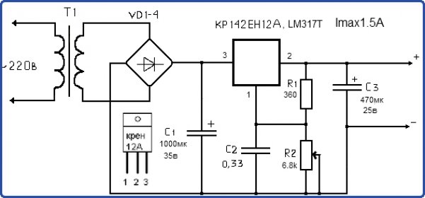
The microcircuit itself is an adjustable compensation type stabilizer. Its pin 1 is the point to which the reference voltage is applied, which determines its value at the dimmer output. The adjustment is made using resistor R2, which is a classic energy dissipator.
Knowing the principle of constructing circuits that control the brightness of lamps, you can not only make such a device yourself, but also repair a dimmer purchased in a store.
I’ve been brewing at home for almost 2 years now and I have a 3 kW Chinese heating element, which in reality produces almost 3.5 kW and not every home electrical network can cope with such power, and you don’t always need such a large power, but to reduce the power of the heating element you need dimmer.
I used to have one, but it can’t handle such a powerful heating element, it overheats and starts to “stink,” so I started looking for something more powerful and found it on eachbuyer.com.
The dimmer arrived quite quickly in 20 days in an unusually silver package: 
Appearance of the dimmer and comparison of sizes with a memory card: 
I immediately decided to disassemble the dimmer. The fuse is very good, but the jumper on the board confused me at first, and then confused me even more when I saw that it was parallel to the fuse, I wonder if offset is needed then? In general, I removed this jumper... The soldering is not bad enough, the flux has been washed off. The BTA80800V triac is mounted on the radiator through thermal paste, I did not find a clear description on the Internet, for some reason only BTA80-800 (800V at 80 W) is found: 
The height of the radiator is 8 cm, which I think is not bad, but the fact that the dimmer does not have a closed housing is of course a huge minus, although with straight hands all this can be solved: 
Between the board and the base of the case is approximately 5 mm: 
Dimmer weight 177 grams: 
Connection
At first there were problems with the connection, because... It’s not clear where to supply power and where to connect the heating element, but a smartphone + Google translator helped a lot, which translated the hieroglyphs using a camera and this is what happened:
I connected the power and the heating element to the dimmer with terminals, I also had to put on the heat shrink, but as they say - “a good thought comes later”...

This is the design I came up with:

It's time to start testing))
I will take readings with a network wattmeter: 
I set the regulator knob (variable resistor) to the extreme left position, place the heating element in the water, turn it on... The wattmeter showed 4.6 W, most likely this is consumption by the thermostat: 
I turn the knob slightly and the power changes smoothly: 
As you can see in the photo above, the maximum power of the heating element is 3.2 kW, and the power up to this limit can be set to any value...
To make sure that the heating element is working, I provide a photo, it shows how the heating element began to become covered with bubbles, the maximum power is set there: 
When I returned the control knob back to the extreme left position, the power remained at 100 W: 
During testing (about 10 minutes) at full power, the radiator heated up to only 40 degrees: 
I tested the dimmer later within an hour, the temperature of the triac did not rise above 60-70 degrees, the radiator warmed up to a maximum of 50 degrees, which I think is not bad at all, and most importantly there was no burning smell.
Let me summarize:
+ I doubt that the dimmer is 9.5 kW, but for my purposes (3.5 kW) it will do
+ doesn’t get very hot
+ you can set the desired power from 0 to the maximum limit of the heating element
+ good soldering
- it is not clear why the jumper is connected in parallel to the fuse
- the terminals could be written in English
- quite a high price, although when I bought the dollar exchange rate was almost 15 rubles cheaper, so the price was quite suitable for me.
Conclusions: Although the dimmer has its drawbacks, I still liked it; it will be very useful for brewing.
I like the store eachbuyer.com, a lot interesting products, there are good discounts, Russian-speaking customer support, fast dispatch and delivery, but their prices are not always low. And most importantly, the dollar exchange rate in the store is a little more than 41 rubles, so I recommend buying in rubles.
Thank you for your attention! I will answer questions whenever possible.
I'm planning to buy +33 Add to favorites I liked the review +26 +53All kinds of dimmers produced by industry can expand the functionality of almost any lighting fixtures and increase their efficiency. But if the situation is not typical, for example, if small sizes are important, then only a homemade device can help.
In addition, making can be a cheaper option than buying, which is extremely convincing. We will tell you how to assemble a dimmer with your own hands. The article we have presented describes in detail what components will be required and in what sequence the work should be performed.
Factory dimmers can provide the expected economic result or increase living comfort in all typical situations. In addition, their prices vary, which will allow you to make a purchase that suits your pocket.
But still, in a number of situations, you may not be able to find an option that is suitable in size or power, so homemade products may be the solution.
In most cases, an interested person will be able to purchase an inexpensive factory dimmer, the performance qualities of which will satisfy him
Meet non-standard situations when industrial products do not satisfy human needs. For example, this happens if you need a small one, and there is a desire to improve the aesthetic properties of its control panel.
Or a person considers it necessary to increase efficiency, make operation more convenient, achieve some color effects, or improve any other characteristic.

Making a simple dimmer is not a difficult task, especially since you only need tools that are accessible to everyone, the main one of which is a soldering iron
You can also perform the assembly yourself if you have the necessary components, which will significantly reduce the cost of the procedure.
What you need to know about dimmers?
The verb "to dim" in English means “to become dim”, “to darken”. This phenomenon is the essence of brightness controls. In addition, a person additionally receives a number of benefits.
Advantages of using the device
Among the advantages, the following additional features should be highlighted:
- reduce energy consumption - this leads to greater efficiency;
- replace several types of lighting fixtures - for example, one lamp can serve as a night floor lamp, main lighting, etc.
In addition, the user can get various lighting effects, for example, use ordinary lighting controlled by a dimmer as light music.
And also its functionality allows you to work in conjunction with security systems or simply simulate the presence of people in the room. This will help owners of any premises protect their property from intruders or even prevent their unauthorized entry into an apartment or office.

The basis of the dimmer design is a triac. It is important to remember that its power should be 20-50% higher than the same load. In addition, it must withstand a voltage of 400 V. This will ensure the product's durability
Additionally, a brightness control can make control of lighting sources and other electrical appliances more convenient and efficient. For example, you can use radio or infrared signals, which will allow you to perform the necessary manipulations remotely.
Or it is possible to use several lighting control points instead of one. For example, if the user wants to make the lighting in the bedroom more modern, then controls can be installed at the entrance there, as well as near the bed.
Such a solution will make the life of the owners somewhat more comfortable. You can do the same in any other room.
How is regulation carried out?
If an interested person decides to assemble a dimmer on his own, then the procedure should begin not with thinking about how to do it, but with defining the goals and tasks that will be solved.

This is what a regular current sinusoid looks like, and the point of dimming is to “cut” it. This will reduce the pulse duration and allow the electrical appliance to operate at less than full power.
So, before you begin assembly, you need to decide what type of lamps will be used. This procedure is mandatory because there are different principles for controlling the brightness of the glow.
These include:
- voltage change- this method will be relevant when using outdated incandescent lamps;
- pulse width modulation- this option must be used to control the brightness of modern energy-saving lighting devices.
Changing the voltage of LED lamps is ineffective due to the fact that they operate in a narrow range and with a slight deviation from the norm they simply go out or do not turn on. What will prevent you from reaching your full potential? conventional devices, that’s why they produce specialized ones for them.
In addition, the use of simple but outdated rheostats does not make it possible to save on electricity. After all, excess electricity in the form of heat is simply dissipated in the air.

A properly made dimmer should provide just such a sinusoid, in which short pulses alternate with long pauses. Moreover, the longer it is, and the signal strength is lower, the dimmer the lamp will glow
Using pulse-width modulation, it will be possible to assemble a brightness controller that provides the lamps with the ability to operate at 10-100% of their power. In this case, the user will receive a pleasant bonus in the form of saved electricity.
You can also take full advantage of all the other advantages of dimmers, including durability.
Relative simplicity of design
Despite the fact that household brightness regulators allow you to obtain a noticeable visual and economic effect, they are characterized by a simple design.
This ensures a long service life, and in the case when a person decides to perform self-assembly, then the simplicity of this operation. As a result, almost anyone can cope with it, even without special knowledge.

A homemade dimmer can be used in different areas, but it should be taken into account that its production will not end with one soldering of components. Since the homemade product will need to be given an attractive appearance
Thus, the most popular modern dimmers are created based on just a few elements:
- dinistor, its other name is often found - diak;
- triac, otherwise known as triac;
- pulse formation unit.
In addition, the design requires the presence of several minor parts, without which work is impossible. These include capacitors, resistors (DC, AC). Each of the main listed semiconductor devices performs its part of the job of controlling the brightness of the lamps.
A triac is often compared to an electrical door, which can be entered in both directions. That is, it is possible to pass current to the lamps in an unlimited amount, but, if necessary, return its excess back.
This process is carried out by an anode with a cathode. They change places depending on the direction of movement of electricity. In addition, a multi-layer conductor design is provided, which allows you to perform tasks as accurately as possible.
The direction switching itself is performed by a dinistor, which is a bidirectional diode.
Factors that complicate the scheme
A person who wants to assemble a dimmer himself should think not only about purchasing the necessary semiconductors. Since the design will need to provide control, placement and even sufficient aesthetic properties, a number of points must be taken into account.
These include:
- type of management;
- placement method;
- appearance.
Since the listed points significantly affect the performance characteristics of the brightness control, each of them should be dealt with separately. This will allow you to get the job done efficiently.
Existing types of device control
Since the dimmer will need to be controlled, the person should choose best option. Because there are many of them and each has its own characteristics, advantages and disadvantages. This will significantly affect the design.
Manipulations can be performed in any of the following ways:
- mechanical;
- electronic;
- remote.
But most often, for all kinds of homemade dimmers, the first option is used. Since the mechanical control is the simplest to assemble, and when purchasing components you will have to pay the least.

The dimmer diagram makes it possible to understand how it works. Namely, when current appears in the network, it, passing through resistors and one of the built-in diodes, charges the capacitor. Excess voltage from which goes to the dinistor and triac. The load transferred to the lamps depends on its position
In this case, the person will only need a regulator, which can be a rotary lever. If desired, it can be replaced with a pressure element. In this case, all manipulations will be performed with ordinary keys, familiar from traditional switches.
Combined rotary-push devices are often used. They make it possible to perform the on/off operation with keys, and the adjustment itself - with a rotary lever. Which many users find convenient.
Any of these options can be similar in size and appearance to a conventional switch, which will allow you to replace such a device. This is another advantage. Electronic control involves the use of sensors to perform all necessary manipulations. They are also shaped like traditional switches and can easily replace them.
Over mechanical analogues, touchscreens have a significant advantage in the form of a modern appearance. The other side of the coin will be the higher cost of components. Remote control the most comfortable, convenient, it is performed using conventional remote controls.
There are different types of command signal transmission:
- radio signal;
- infrared signal.
In the first case, the user will be able to make the necessary adjustments from anywhere in the building, room, and even from outside. Which is convenient and effective, but the components will cost more than when buying a remote control with an infrared signal.
The signal is capable of transmitting necessary information only when hovering over itself. And this can only be done within one room.

A simpler option is the hinged version of the brightness control assembly. And the most durable is the printed circuit board, which will prevent many types of premature failure
However, this feature is usually not considered a disadvantage, which is why more affordable kits with an infrared signal are more popular. Remote control methods also include acoustic ones, but in this case you will have to purchase a sensor capable of capturing sound commands: clapping hands, sounds of music and other similar noises.
Still, you should know that the latter option is more spectacular than effective. Since any third-party sounds, for example, the barking of a pet, a loud conversation will lead to an unauthorized change in the brightness of the lamps. This will not always please users.
At the same time, an acoustic sensor built into the dimmer design can make any party unforgettable, as it makes the lighting fixtures respond to changes in the volume of the music. That is, in this way, it is quite possible to replace light and music.
In addition, you should know that control options using a computer with wired or wireless connection, as well as a smartphone or tablet, which transmit the required command signal via Wi-Fi.

Printed circuit boards are compact and durable compared to wall-mounted circuits. In addition, they are safer, which is important, since dimmers are used in rooms where people are present.
To be able to use any of the listed methods, the dimmer design must be equipped with the necessary elements. Which makes it more complicated, and therefore more expensive. As a result, the most popular control option traditionally remains mechanical.
Device placement type
Any modern dimmer can be placed in only three ways, and in everyday life, a total of fewer are used - only 2. One option is rarely in demand due to its design complexity and performance.
Therefore, for residential or small commercial premises the following types of accommodation are used:
- invoices;
- built-in
In the first case, a traditional switch is replaced with a dimmer; in the second, it is installed out of sight, that is, mounted in a transfer case, a specially made niche. This means that in one situation a person needs to take care of a control panel with high aesthetic qualities.
And in another, this nuance does not play any role. Since the device will be hidden from view. But you will have to use only the remote control method. Invoices are mainly of mechanical or electronic varieties.
Dimmer operating principle
The most effective way to control brightness is using pulse width modulation. Since it is most suitable for modern .
The principle of operation in this case is the supply of current in short pulses, between which there is a long pause. Moreover, the longer its duration, the lower the brightness of the glow.

Connecting the regulators is an important stage of assembly, since functionality and comfort depend on it, which is why people do this kind of work
At the same time, the simplest devices are capable of changing the characteristics of light by simply decreasing/increasing the applied voltage. But this option will only be beneficial when using incandescent lamps.
In the case of using LED devices paired with the device, they will only be able to work, since ordinary LEDs are not adjustable.
Making your own dimmer
Initially, you have to decide on a number of parameters, including power, type of placement, control. Without this procedure, a functional regulator can only be created by accident, which is rare.
In addition, you will need a capacitor and 2 resistors capable of supporting the previously determined power. Moreover, one of them must be variable. This feature will allow you to change the voltage.

The diagram shows how the user can control one light source using two regulators installed in different parts of the room, which is convenient
And when its value reaches the maximum possible for the dinistor used, it is triggered and supplies the necessary command impulse. Which is sent to the triac, and then goes to lamps or other electrical appliances.
When this power switch opens depends on the position of the controls. Since it can be either 220 V or 40 V, if a person needs it.

Since craftsmen mainly make overhead dimmers, installing it in a circuit is not difficult. Since this operation is no different from installing a traditional switch
All of the above structural elements are connected into one product according to the attached diagram using wires and soldering. Contacts must be carefully insulated. Because short circuit- one of several common causes of electrical equipment failure.
Connecting the dimer to the circuit
This is no less important part of the work than the manufacturing itself, since the durability of operation largely depends on the quality. In addition, the connection affects the convenience and comfort of control, so dimmers are usually divided according to this characteristic.
They are as follows:
- by type of switch - they replace traditional switches and regulate one lamp or a group of them, for example, a chandelier with a large number of lighting elements;
- walk-through - allow you to control one electrical device, for example, an LED lamp, using several regulators, for convenience, located in various parts premises, buildings.
In the first case, when using a network that includes 3 wires, zero and ground go to the lamp, another electrical appliance, and the phase goes to break. That is, the procedure is familiar to everyone who has replaced conventional switches.

When checking the regulator, its installation and operation, a person should observe safety precautions, since sufficient voltage passes through it to cause harm to health
When installing two pass-through dimmers, three wires should be connected to each of them from the junction box. This is a must. The first two pins are then used to connect both regulators. A jumper should be used to ensure reliability.
Another of the free contacts is connected to the phase, and the last one to the lighting fixture. After which the connection is checked for functionality.
During these operations, you should remember to observe safety measures - each of them can only be performed after the network has been de-energized.
With guidelines for choosing a dimmer for control LED strip will introduce you, completely dedicated to this interesting topic.
Conclusions and useful video on the topic
The first video will help you quickly understand the manufacturing procedure:
The following video material will allow you to familiarize yourself with the principle of operation of modern dimmers:
Any user, even those without special skills, will be able to figure out how to properly make a simple dimmer with their own hands. This is a very inexpensive and uncomplicated solution. The main thing is to select elements of the required power and connect them together efficiently.
At the same time, it will be necessary to give the product a decent appearance, which complicates the task. But for this purpose, you can use the housings of industrial regulators, even used ones.
I welcome everyone who stopped by. The review will focus, as you probably already guessed, on a very useful power regulator/dimmer, rated for 2000W and allowing you to adjust the output power of various devices. The adapter is very useful in everyday life, it has a lot of applications, so anyone interested, you are welcome under the cat...
Upd, added a couple of tests with a higher load
General view:
Brief technical characteristics:
- Maximum power – 2000W
- Supply voltage – 50-220V
- Housing - no
- Dimensions - 52mm*50mm*30mm
- Weight – 41g
Dimensions:
The power controller/dimmer comes in a standard bag and is small in size. Here is a comparison with a thousand dollar note and a box of matches: 

Appearance:
The regulator has only one working element, which allows you to change the output power more or less: 
The number of parts is small, the soldering is good, the flux has been washed off: 
To connect to the network/devices, a terminal block with protective sides is soldered on the board: 
The connection is simple: two left terminals (IN) for connecting to a 220V network, two right terminals (OUT) for connecting a load.
Unfortunately, the device does not have any housing, so be careful when using it in this form!
Testing:
As an example, let's try to regulate the power of the EPCN-40 soldering iron, with a power of 40W: 
We will monitor the parameters with a homemade wattmeter: 
In nominal mode, the soldering iron consumes about 39W: 
The minimum possible power with this regulator was 10W: 
The maximum possible power through the regulator is 38W: 
The difference of 1-2W can be offset by losses in additional wires and different input voltages, i.e. When the regulator is set to MAX, the output power is almost unlimited.
Many people will ask, why change the power of the soldering iron. My answer is to minimize tip burnout. With much smaller sizes tip or at high power of the soldering iron, when it is in the “standby” mode for a long time, the tip “burns out”. If you constantly turn off the power to the soldering iron, you will need to wait several minutes for it to heat up to the desired temperature again. Agree – it’s not very convenient. This regulator, in turn, only slightly reduces the temperature and, if necessary, in order to bring the soldering iron parameters to nominal, it will take much less time than with full heating. At the same time, the wear of the tip is small, it warms up to the nominal temperature in half a minute. In the photo below the power is set to about 30W: 
At the request of readers, I am adding a small test with a more powerful load, which is a KLT-3A hot air gun. A homemade wattmeter was connected to the output of the regulator.
With a load of 700W (the regulator slider is set to MAX), the triac radiator is warm, in 5 minutes it heated up to 35°C: 
It can work in this mode for a long time. In the second mode of the hot air gun (control slider at MAX), the temperature reached 50°C in a minute. The power was about 1350W: 
With such power, this radiator is not enough for long-term operation; it is necessary to attach a more massive radiator or active cooling (cooler). In my opinion, up to 800-900W you can use the regulator “as is”; at higher powers and long-term operating modes, the cooling needs to be modified!
A couple more examples, the regulator is set to the middle position: 
Slightly above average: 
Very common applications of the regulator:
- Change in revolutions of commutator motors:
Suitable as a budget regulator for most power tools (angle grinders/grinders, drills, hammer drills, planes, sanders). A very convenient thing for models that do not have a built-in speed controller or soft start systems, for example, the same budget angle grinders with a nominal spindle speed of 11,000 rpm. The only thing you need to remember is that as power decreases, the torque on the shaft also decreases, plus the cooling system is designed for rated speeds and will not cool properly at reduced speeds. There is a risk of burning the instrument due to overheating
- Adjusting the power of lighting lamps is an indispensable thing when turning off a certain group of lamps is unacceptable. The regulator allows you to smoothly change the brightness of the glow in the right place
- Adjusting the power of heating devices: heating elements, soldering irons
Total, the regulator is good, the radiator practically does not heat up at low powers (up to 800-900W), at higher powers it is advisable to improve the cooling and traces on the board. The regulator is cheap, recommended for purchase...
The product was provided for writing a review by the store. The review was published in accordance with clause 18 of the Site Rules.
I'm planning to buy +78 Add to favorites I liked the review +54 +103

