How to make the LED blink. Making a flashing LED with your own hands: simple and complex circuits
We present to your attention probably the simplest, but most interesting LED flasher circuit. If you have a small Christmas tree made of shiny rain, then a bright 5-7 cd LED mounted in its base that not only lights up, but also blinks is a very simple and beautiful decoration for your workplace. The circuit is powered by 3-12V, can be replaced by power from USB port. The previous article was also about an LED flasher, but unlike it, this article will tell you about a single LED flasher, which in no way narrows its scope, I would say even the opposite. Surely you have seen a winking green, red or blue light more than once, for example, in car alarm. Now you have the opportunity to assemble a simple LED flasher circuit. Below is a table with the parameters of the parts in the circuit for determining the flash frequency.
In addition to this application, you can use the LED flasher as a car alarm emulator. Installing a new car alarm is not a simple and troublesome task, but having the specified parts on hand can be quickly assembled LED flasher circuit and now your car is “protected” for the first time. At least from accidental hacking. Such a “car alarm” - an LED flashing in the crack of the dashboard will scare off inexperienced burglars, because this is the first sign of a working alarm? You never know where else you will need a flashing LED.
The frequency with which the LED lights up depends on the resistance of resistors R1 and R2 and the capacitance of capacitor C1. At the time of debugging, instead of resistors R1 and R2, you can use variable resistors of the corresponding values. To slightly simplify the selection of elements, the table below shows the ratings of the parts and the corresponding flash frequency.

If a flasher on an LED refuses to work at certain values, you must first of all pay attention to resistor R1, its resistance may be too low, and also to resistor R2, its resistance may be too high. The duration of the pulses themselves depends on resistor R2, and the duration of the pause between pulses depends on resistor R1.
The LED flasher circuit with minor modifications can become sound pulse generator. To do this, you will need to install a speaker with a resistance of up to 4 ohms in place of resistor R3. Replace LED HL1 with a jumper. Use a transistor of sufficient power as transistor VT2. In addition, it is necessary to select capacitor C1 of the required capacity. The choice is made as follows. Let's say we have elements with parameters from row 2 of the table. Pulse frequency 1Hz (60 pulses per minute). And we want to get sound with a frequency of 1000Hz. Therefore, it is necessary to reduce the capacitance of the capacitor by 1000 times. We get 10 µF / 1000 = 0.01 µF = 10 nF. In addition, you can play with decreasing the resistance of the resistors, but don’t get too carried away, you can burn the transistors.
One of our regular readers, especially for our site, suggested another option for a very simple LED flasher. Watch the video:
I present 3 flashing light schemes and 2 color music schemes. The first one is for 2 LEDs, the rest are for one.
Transistors KT209M pnp type. You can also use npn by changing the polarity of the power supply, LEDs and capacitors.
There are similar symmetrical multivibrator circuits on the Internet, where the transistors are connected by the emitters and the collectors are at the top, for example, as in this sound generator circuit: The circuit is assembled on a plastic card.
Second scheme consists of two transistors pnp and npn, one resistor, capacitor and LED. It is powered by two AA batteries, like all the circuits in this review. Transistors: KT3107I and KT3102B (or maybe L(I) - the color is not clear), also for some reason the dark green dot is on the round side of the transistor, and not on the flat side, as indicated in all reference books.

To view in a larger size, you need to click on the link with the name of the video, or on the YouTube button during playback!
In the third scheme a second resistor has been added. The blinking parameters in all circuits can be adjusted by changing the capacitance of the capacitors and the resistance of the resistors.

To view in a larger size, you need to click on the link with the name of the video, or on the YouTube button during playback!
The LED flashes to the music from your computer or any other music device. Connects to one of two audio channels. The circuit uses an NPN transistor C9014, a 10 kOhm resistor, and a powerful 3 W LED. Powered by a 3.7 V lithium battery.

Instead of a battery, you can use 5 Volts from the system unit's power supply. The brightness is changed by selecting the resistor resistance, supply voltage and volume on the computer.
To view in a larger size, you need to click on the link with the name of the video, or on the YouTube button during playback!
The video uses a powerful LED with a permissible maximum current of 700 mA at a voltage drop of 4 V. Therefore, if you take a regular LED with a current of 20 mA, it is important not to allow this current value to be greatly exceeded.
The second color music scheme is, in my opinion, less successful, but maybe it will be useful to someone. I am publishing a photo with signed details.The resistance of the resistor and the capacitance of the capacitor can be changed.
 New articles have been added to the second site, which can be accessed through the "Spectroscopy" button in the site menu!
The blinking light signal is widely used - from a special mode of operation of flashlights to the indication of complex equipment. It is increasingly based on a flashing LED, as a reliable and durable alternative to any other types of light sources.
Let's consider what its principle of operation is, what ready-made solutions for such a device are available on the market today, how to make an ice element operating in normal mode begin to work in a flickering rhythm, what is the general scope of their application, as well as how to do it yourself using them make garlands and running lights.
An LED with flashing light emission is a standard LED crystal, the electrical power circuit of which includes a capacitance and a resistor that determine the operating mode. Externally, it is no different from ordinary analogues. Moreover, the mechanism of its operation is at the level of processes occurring in electrical circuit, comes down to this:
- When current is applied to resistor R, charge and voltage accumulate in capacitor C.
- When its potential reaches 12 volts, a breakdown is formed at the p-n boundary in the transistor. This increases conductivity, which initiates the production of light flux by the ice crystal.
- When the voltage drops, the transistor turns off again and the process begins again.
All modules of such a circuit operate at the same frequency.
Ready flashing LEDs
Flashing LEDs from various manufacturers are essentially functionally complete circuits, ready for use in various fields. In terms of external parameters, they are not much different from standard ice devices. However, their design includes a generator-type circuit and its accompanying elements.
Among the main advantages of ready-made flashing LEDs are:
- Compact, robust housing, all components in one housing.
- Large range of supply voltage.
- Multi-color design, wide variety of shade switching rhythms.
- Economical.
Advice! The simplest flashing LED can be made by connecting an LED crystal, a CR battery and a 160-230 Ohm resistor into one chain, observing the polarity rules.
Usage patterns
The simplest version of the circuit of LED-based flashers produced today, which can be manufactured by radio amateurs on their own, includes:
- Low power transistor.
- Polar type capacitor 16 volts and 470 microfarads.
- Resistor.
- Ice element.

When the charge accumulates, an avalanche-like breakdown occurs with the opening of the transistor module and the glow of the diode. This type of device is often used in Christmas tree garland. The disadvantage of the circuit is the need to use a special power source.
Read also How to properly connect an LED to a 220 V network
Another version of flashing type LED circuits that are popular today includes a pair of npn transistors of the KT315 B modification. The following components are also used for its assembly:
- Two pairs of resistors for 6.8–15 kOhm and 470–680 Ohm.
- Two capacitors with a capacity of 47-100 µF.
- A small LED or a piece of ice strip.
- Power supply from 3 to 12 V.

The principle of operation of the device is determined by an alternating change in the charging/discharging cycle of capacitors, which in turn open the transistors and power the LEDs and ensure their blinking.
Conventional LEDs
The standard non-blinking LED provides bright, uniform illumination and low power consumption. Along with such qualities as durability, compactness, energy efficiency and a wide range of glow temperatures, this makes it unrivaled among other artificial light sources. A circuit of flickering lamps is assembled on the basis of such LED elements. Let's look at the principle by which they are made.
How to make LEDs blink
An LED flasher can be assembled based on one of the above presented circuits. Accordingly, you will need to purchase the components described above. They are necessary for the functioning of one or another option. In this case, for assembly you will need a soldering iron, solder, flux and other necessary components for soldering.
The assembly of a chain of flashing LEDs is preceded by the obligatory tinning of the output contacts of all connected elements. Also, we must not forget about observing polarity rules, especially when connecting capacitors. The finished lamp will flicker with a frequency of about 1.5 Hz or, which is the same, about 15 pulses every 10-second period of time.

Flasher circuits based on them
In order for elementary flashes of light to occur at a certain periodicity, a pair of C945 type transistors or analog elements is required. For the first option, the collector is placed in the center, and for the second, the base is located in the middle. One or a pair of flashing LEDs are manufactured according to the usual design. In this case, the frequency of flashes is set by the presence of capacitors C1 and C2 in the chain.
It is permissible to introduce several ice crystals simultaneously into such a system during installation. powerful transistor pnp type. In this case, the LEDs are made to blink when their contacts are connected to multi-colored elements, the sequence of flashes is set by the generator module, and the frequency is set by the specified software settings.
Scope of application
LEDs operating in a flashing rhythm are used in various fields:
- In the entertainment field, in toys, for decoration, as garlands.
- As an indication in household and industrial devices.
- Light signaling devices.
- In advertising elements, signs.
- Information boards.
Important! LEDs, which emit light in a blinking rhythm, are used not only in the visible range of the spectrum, but also in the infrared and ultraviolet segments. Their area of purpose is automation systems and remote control various equipment– heating, ventilation, household appliances.
DIY LED running lights
One of the areas of use of flashing LEDs is the “running lights” device. The following components are used to assemble the circuit:
- Rectangular pulse generator.
- Display device.
- Decoder.
- Counter.
Perfection is not achieved when there is nothing left to add,
and then when there is nothing to remove.
Antoine de Saint-Exupéry
Many radio amateurs, of course, have encountered SMT (Surface mount technology) printed circuit board technology, met SMD (Surface mount device) elements mounted on the surface and heard about the advantages of surface mounting, which is rightly called the fourth revolution in electronic technology after the invention lamp, transistor and integrated circuit.
Some people consider surface mounting difficult to implement at home due to the small size of SMD elements and... the lack of holes for parts leads.
This is partly true, but upon careful examination it turns out that the small size of the elements simply requires careful installation, of course, provided that we are talking about simple SMD components that do not require special equipment for installation. The absence of reference points, which are holes for the pins of parts, only creates the illusion of difficulty in making a printed circuit board design.
You need practice in creating simple designs on SMD elements in order to acquire skills, self-confidence, and be convinced of the prospects of surface mounting for yourself personally. After all, the process of manufacturing a printed circuit board is simplified (there is no need to drill holes or mold parts leads), and the resulting gain in installation density is noticeable to the naked eye.
The basis of our designs is an asymmetrical multivibrator circuit using transistors of various structures.
We will assemble a “flashing light” on an LED, which will serve as a talisman, and we will also create a foundation for future designs by making a prototype of a microcircuit that is popular among radio amateurs, but not entirely accessible.
Asymmetrical multivibrator using transistors of different structures
(Fig. 1) is a real “bestseller” in amateur radio literature.
Rice. 1. Single-ended multivibrator circuit
By connecting certain external circuits to the circuit, you can assemble more than a dozen structures. For example, a sound probe, a generator for learning Morse code, a device for repelling mosquitoes, the basis of a one-voice musical instrument. And the use of external sensors or control devices in the base circuit of the VT1 transistor allows you to obtain a watchdog device, an indicator of humidity, illumination, temperature and many other designs.
--
Thank you for your attention!
Igor Kotov, founder of Datagor magazine
List of sources
1. Mosyagin V.V. Secrets of amateur radio skills. – M.: SOLON-Press. – 2005, 216 p. (pp. 47 – 64).2. Shustov M.A. Practical circuit design. 450 useful diagrams for radio amateurs. Book 1. – M.: Altex-A, 2001. – 352 p.
3. Shustov M.A. Practical circuit design. Monitoring and protection of power supplies. Book 4. – M.: Altex-A, 2002. – 176 p.
4. Low-voltage flasher. (Abroad) // Radio, 1998, No. 6, p. 64.
5.
6.
7.
8. Shoemaker Ch. Amateur control and signaling circuits on ICs. – M:.Mir, 1989 (diagram 46. Simple low battery indicator, p. 104; diagram 47. Painter marker (flashing), p. 105).
9. Generator on LM3909 // Radio circuit, 2008, No. 2. Diploma specialty - radio engineer, Ph.D.
Author of the books To a young radio amateur for reading with a soldering iron”, “Secrets of amateur radio craftsmanship”, co-author of the series of books “For reading with a soldering iron” in the publishing house “SOLON-Press”, I have publications in the magazines “Radio”, “Instruments and Experimental Techniques”, etc.
Reader vote

The article was approved by 66 readers.
To participate in the voting, register and log in to the site with your username and password.There is no great need to assemble a flashing LED with your own hands. Such diodes have been on sale for a long time different models and colors, and their operation does not require additional control devices. In this micro-light bulb, a circuit is soldered inside the bulb, thanks to which the blinking occurs. But a radio amateur is not interested in buying ready-made equipment; he wants to make it himself.
Unlike the operation of a conventional LED, a capacitor is added to the circuit. It accumulates energy, after which an avalanche breakdown occurs and the diode lights up for a split second. Then it charges again - and again there is a breakdown. This is how flashing occurs.
The simplest diagram looks like this:
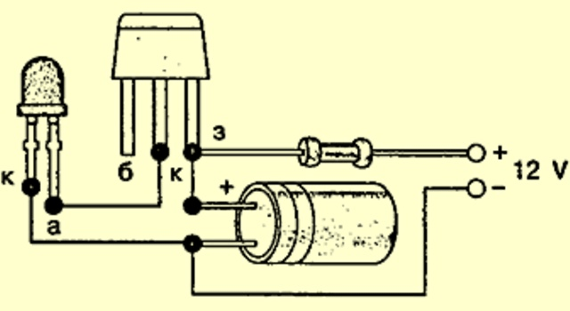
How to make an LED flasher with your own hands
Let's return to the diagram. It involves (from left to right): an LED, a KT315 type transistor, a 1 kOhm resistor and under it an electrolytic capacitor of 16 volts and a capacity of 1000-3000 microfarads.
Now let's see how such a simple flasher is assembled.
What do you need
- Soldering iron with a thin tip, rosin and solder.
- Transistor KT315 or equivalent.
- LED
- A 12 volt power supply (better regulated) or another source with the same voltage.
- Any housing for your flasher or structure in which you will mount the diode (optional; for a trial assembly, you can choose a matchbox).


Flasher assembly sequence
We will move from the power source.
- We solder a resistor to the “+” terminal from the source.
- We solder the free contact of the resistor to the emitter of the transistor. How to identify the emitter and other contacts, watch the video:
- Next, we connect the emitter to the “+” terminal of the capacitor. You can determine plus and minus by the markings on the case. The minus is indicated by a light stripe.

- The next stage is connecting the “collector” contact of the transistor to the “+” terminal of the diode. KT315 has such a contact in the middle. The positive terminal of the diode can be determined visually. Inside its bulb there is a pair of electrodes. The one that is smaller is the plus one.
- There are two steps left. We solder the “-” diode to the “-” power supply and connect the “-” capacitor to the same line.
As a result, you may end up with a test flasher like this:

If the LED does not blink and is on, and your power supply is unregulated, then this problem can be solved by adding additional resistance (adding an additional resistor to the circuit).
Secondly, buy only quality parts.
Chinese analogues not only serve less, they sometimes do not correspond to the declared characteristics.
Thirdly, if you think that an LED flasher is not useful in your everyday life, think carefully and look around. Or search the Internet for information where they are used. You are sure to find something interesting.
If you just decided to master the basics of a radio amateur, then such a question will not arise. Try to assemble simple circuits and move on to complex ones. For example, to the so-called address LED strips, which are already used for serious combinations of flashing light between several LEDs, or even dozens of LEDs.
In conclusion
An experienced radio amateur will always find a use for old parts. Rare transistors, thyristors, resistors, capacitors, diodes and other radio components can be found in used televisions, radios and other equipment.
One craftsman, for example, made a flashing light for a toy fire truck. Why not.
Write comments if you are interested in flashing LEDs. And don’t forget to share the article on social networks!


