Connecting a photoresistor to Arduino and working with a light sensor. Circuit on breadboard
Hi all! I am Artem Luzhetsky and I will be conducting a series of articles dedicated to " Smart home" and IoT (English - Internet of Things, Internet of Things). We will get acquainted with amazing ways to create home network from a variety of devices that will work either autonomously or with human assistance. Well? Let's get started!
The first article is introductory, I want you to understand that I will be working with the most common boards and modules so that most people can try their hand at IoT development.
So, first we need two microcontrollers that we will use: and .
Arduino UNO
I think there is no need to introduce you to this board; it is very popular among beginners and DIY fans. I will only say that the capabilities of this board are limited and UNO cannot work with the https protocol, the ATmega328P microcontroller does not have enough computing power, so when we have to work with the microcontroller and the https protocol, we will program the ESP8266.
ESP8266

I will work with the Troyka ESP8266 module from the Amperka company, but you can safely use the regular ESP 8266 module, they have practically no differences, the main thing when connecting is to look at the meaning of the pins and remember that the ESP operates on 3.3 volt logic, so you need to either connect via 5 volts, but connect a voltage stabilizer to the circuit, or simply use a pin with a voltage supply of 3.3 volts.
This microcontroller is not the most powerful in the Espressif series on the general market, but it is one of the cheapest and most common. It will be the basis of our IoT developments.
Additional details
We will also need to create all experiments:
- LEDs
- Photoresistor
- Thermistor
- Ultrasonic range finder
- Piezodynamic
- Mini Servo
- IR sensor
- IR remote control
We don't need to have all of these modules to work with IoT, but in order to do all future projects, we will eventually have to purchase them all.
Programs and libraries
First, download the library that will help you work much easier in the Arduino IDE if you use an ESP8266 - http://wiki.amperka.ru/_media/iot-m:iot-m-libs.zip
Second, to better understand IoT, we will need websites that will give us the ability to send data to them.
- www.dweet.io
- maker.ifttt.com
- narodmon.ru
- etc.
Third, we will also need various Android applications so that we can control a smart home using our phone.
- OpenHab
- Blink
- etc.
We will get acquainted with all the methods, programs and sites in detail in the upcoming projects.
2. Making a “smart lamp”
Have I already made you bored? Let's make the simplest smart lamp that will turn on if the room is dark.
In fact, you don't even need a UNO for this, you can use a digital custom photosensor, but in the future we will change this project beyond recognition, so we will have to start somewhere.
If you are not sure that you are ready to work with 220 volt electricity, then use a regular LED instead of a flashlight. At the beginning, I took my old TLI-204 lamp, these are available in almost any store (I unplugged it in advance).

The lamp has two types of operation (on/off), what I want to do is I want to increase its functionality, leave the ability to completely turn the lamp on and off.
It will not be possible to connect a photoresistor with a relay in parallel to a circuit without using another switch, so I decided to install a three-position toggle switch instead of a two-position switch.

General electrical diagram should look like this:

If everything is done correctly, then in the third position of the switch you can, by supplying current to the relay from the microcontroller, turn on the lamp.

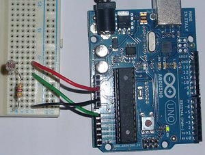
Let's connect a photoresistor to the Arduino. The diagram looks like this:

3. Code for "smart lamp"

Now let's write a code that will transfer current to the relay if the room is dark.
#define SHINE 5 //PIN ON PHOTORESISTOR #define REL 13 //PIN ON RELAY void setup())( pinMode(SHINE, INPUT); pinMode(REL, OUTPUT); Serial.begin(9600); ) void loop())( if (analogRead(SHINE)<600) // Если света в комнате мало, то включаем лампу { digitalWrite(REL, HIGH) } else // если много, то выключаем { digitalWrite(REL, LOW); } Serial.printIn(analogRead(SHINE)); selay(500); }
When you connect everything, remember to remove the photo sensor from the llama, otherwise you will be treated to a light show. Everything should work.
Next time we will try to complicate the code and add a couple more functions. See you soon!
For an additional task
1 more LED
1 more resistor with a nominal value of 220 Ohms
2 more wires
Schematic diagram
Scheme on the breadboard

Please note
In this experiment we install a photoresistor between the power supply and the analog input, i.e. to position R1 in the voltage divider circuit. We need this so that when the illumination decreases, we receive less voltage at the analog input.
Try to place the components so that the LED does not illuminate the photoresistor.
Sketch
p050_night_light.ino #define LED_PIN 13 #define LDR_PIN A0 #define POT_PIN A1 void setup() ( pinMode(LED_PIN, OUTPUT) ; ) void loop() ( // read the light level. By the way, announce // you can assign a variable and a value to it at once int lightness = analogRead(LDR_PIN) ; // read the value from the potentiometer with which we regulate // threshold value between conditional darkness and light int threshold = analogRead(POT_PIN) ; // declare a boolean variable and assign a value to it // “Is it dark now.” Boolean variables, as opposed to // integers, can contain only one of two values: // true or false. Such values // also called boolean. boolean tooDark = (lightness< threshold) ; // use program branching: the processor will execute one of // two blocks of code depending on the execution of the condition. // If (English “if”) is too dark... if (tooDark) ( // ...turn on the lighting digitalWrite(LED_PIN, HIGH) ; ) else ( // ...otherwise the light is not needed - turn it off digitalWrite(LED_PIN, LOW) ; ) )
Explanations for the code
We use a new type of variable - boolean, which stores only the values true (true, 1) or false (false, 0). These values are the result of evaluating Boolean expressions. In this example, the Boolean expression is lightness< threshold . На человеческом языке это звучит как: «освещенность ниже порогового уровня». Такое высказывание будет истинным, когда освещенность ниже порогового уровня. Микроконтроллер может сравнить значения переменных lightness и threshold , которые, в свою очередь, являются результатами измерений, и вычислить истинность логического выражения.
We put this logical expression in brackets only for clarity. It's always better to write readable code. In other cases, parentheses can affect the order of operations, as in ordinary arithmetic.
In our experiment, the boolean expression will be true when the lightness value is less than the threshold value because we used the operator< . Мы можем использовать операторы > , <= , >= , == , != , which mean “greater than,” “less than or equal to,” “greater than or equal to,” “equal to,” “not equal to,” respectively.
Be especially careful with logical operator== and don't confuse it with the assignment operator =. In the first case, we compare the values of expressions and get a logical value (true or false), and in the second case, we assign the value of the right operand to the left operand. The compiler does not know our intentions and will not issue an error, but we can accidentally change the value of some variable and then spend a long time looking for an error.
The conditional if statement is one of the key ones in most programming languages. With its help, we can perform not only a strictly defined sequence of actions, but also make decisions about which branch of the algorithm to follow, depending on certain conditions.
The logical expression lightness< threshold есть значение: true или false . Мы вычислили его и поместили в булеву переменную tooDark («слишком темно»). Таким образом мы как бы говорим «если слишком темно, то включить светодиод»
With the same success we could say “if the illumination is less than the threshold level, then turn on the LED,” i.e. pass the entire logical expression to if:
For conditional operator if necessarily follows a block of code that is executed if the logical expression is true. Don't forget about both curly braces ()!
If, if the expression is true, we only need to execute one instruction, it can be written immediately after if (...) without curly braces:
The if statement can be extended else construction("otherwise"). The block of code, or the single statement following it, will only be executed if the Boolean expression in if evaluates to false. The rules regarding curly braces are the same. In our experiment, we wrote "if it's too dark, turn on the LED, otherwise turn off the LED."
In this experiment, the LED should turn on when the light level drops below a threshold set by a potentiometer.
LIST OF PARTS FOR THE EXPERIMENT
- 1 Arduino Uno board;
- 1 solderless breadboard;
- 1 LED;
- 1 photoresistor;
- 1 resistor with a nominal value of 220 Ohms, 1 resistor with a nominal value of 10 kOhms;
- 1 variable resistor (potentiometer);
- 10 male-male wires.
DETAILS FOR ADDITIONAL TASK
1 more LED;
Another 1 resistor with a nominal value of 220 Ohms;
2 more wires.
CIRCUIT DIAGRAM
DIAGRAM ON BREADBOARD

SKETCH
download sketch for Arduino IDE#define LED_PIN 13 #define LDR_PIN A0 #define POT_PIN A1 void setup() ( pinMode(LED_PIN, OUTPUT); ) void loop() ( // read the light level. By the way, you can declare // a variable and assign a value to it at once int lightness = analogRead(LDR_PIN); // read the value from the potentiometer, which we use to adjust // the threshold value between conditional darkness and light int threshold = analogRead(POT_PIN); // declare a logical variable and assign it the value // “is it dark now”. Boolean variables, unlike // integers, can contain only one of two values: // true or false. Such values // are also called boolean (boolean tooDark =). (lightness< threshold); // используем ветвление программы: процессор исполнит один из // двух блоков кода в зависимости от исполнения условия. // Если (англ. «if») слишком темно... if (tooDark) { // ...включаем освещение digitalWrite(LED_PIN, HIGH); } else { // ...иначе свет не нужен — выключаем его digitalWrite(LED_PIN, LOW); } }
EXPLANATIONS FOR THE CODE
- We are using a new type of variables − boolean, which store only values true (true, 1) or false (false, 0). These values are the result of evaluating Boolean expressions. In this example, the Boolean expression is lightness< threshold . In human language this sounds like: “illuminance below the threshold level.” Such a statement will be true when the illumination is below the threshold level. The microcontroller can compare the values of variables lightness And threshold, which in turn are the measurement results, and calculate the truth of the logical expression.
- We put this logical expression in brackets only for clarity. It's always better to write readable code. In other cases, parentheses can affect the order of operations, as in ordinary arithmetic.
- In our experiment, a Boolean expression will be true when the value lightness less than value threshold because we used the operator < . We can use operators > , <= , >= , = = , != , which mean “greater than,” “less than or equal to,” “greater than or equal to,” “equal to,” “not equal to,” respectively.
- Be especially careful with the logical operator = = and don't confuse it with the assignment operator = . In the first case, we compare the values of expressions and get a logical value (true or false), and in the second case, we assign the value of the right operand to the left operand. The compiler does not know our intentions and will not issue an error, but we can accidentally change the value of some variable and then spend a long time looking for an error.
- Conditional operator if (« If") is one of the key ones in most programming languages. With its help, we can perform not only a strictly defined sequence of actions, but also make decisions about which branch of the algorithm to follow, depending on certain conditions.
- For a logical expression lightness< threshold there is a meaning: true or false. We calculated it and put it into a boolean variable tooDark(“too dark”) Thus, we seem to be saying “if it’s too dark, then turn on the LED”
- With the same success we could say “if the illumination is less than the threshold level, then turn on the LED,” i.e. transfer to if all logical expression:
if (lightness< threshold) { // ... }
- Behind the conditional statement if There must be a block of code that is executed if the logical expression is true. Don't forget about both curly braces {} !
- If, if the expression is true, we only need to execute one instructions, it can be written immediately after if (…) without curly braces:
if (lightness< threshold) digitalWrite(LED_PIN, HIGH);
- Operator if can be extended by design else("otherwise"). A block of code or a single statement following it will only be executed if the logical expression in if matters false , « lie" The rules regarding curly braces are the same. In our experiment, we wrote "if it's too dark, turn on the LED, otherwise turn off the LED."
QUESTIONS TO TEST YOURSELF
- If we install a photoresistor between the analog input and ground, our device will work in reverse: the LED will turn on when the amount of light increases. Why?
- What result of the device will we get if the light from the LED falls on the photoresistor?
- If we do install the photoresistor as stated in the previous question, how do we need to change the program so that the device works correctly?
- Let's say we have the code if (condition) (action;). In what cases will it be done? action ?
- At what values y expression x + y > 0 will be true if x > 0 ?
- Is it necessary to indicate which instructions to execute if the condition is in the statement if false?
- What is the difference between the operator = = from the operator = ?
- If we use the construction if (condition) action1; else action2;, could there be a situation where none of the actions are executed? Why?
TASKS FOR INDEPENDENT SOLUTION
- Rewrite the program without using the variable tooDark while maintaining the functionality of the device.
- Add another LED to the circuit. Complete the program so that when the illumination falls below the threshold value, one LED turns on, and when the illumination falls below half the threshold value, both LEDs turn on.
- Change the circuit and program so that the LEDs turn on according to the same principle, but glow the more intensely the less light falls on the photoresistor.
For our next project we will be using a photoresistor. And we will consider the implementation of a night light for the bedroom, which will automatically turn on when it is dark and turn off when it becomes light.
The resistance of a photoresistor depends on the light falling on it. Using a photoresistor in conjunction with a conventional 4.7 kOhm resistor, we get a voltage divider in which the voltage passing through the photoresistor changes depending on the light level.
We apply the voltage from the divider to the input of the Arduino ADC. There we compare the resulting value with a certain threshold and turn the lamp on or off.
The circuit diagram of the divider is shown below. When the illumination increases, the resistance of the photoresistor drops and, accordingly, the voltage at the divider output (and ADC input) increases. When the illumination drops, everything is the other way around.

The photo below shows the assembled circuit on a breadboard. Voltages 0V and 5V are taken from Arduino. Pin A0 is used as an ADC input.
Below is an Arduino sketch. In this tutorial we simply turn on and off the LED that is built into the Arduino board. You can connect a brighter LED to leg 13 (via a ~220 Ohm resistor). If you connect a more powerful load, such as an incandescent lamp, then it should be connected through a relay or thyristor.
There are commented sections in the program code, they are used for debugging. It will be possible to control the ADC value (from 0 to 1024). Also, you need to change the value 500 (on and off threshold) in the code to the one you select experimentally by changing the illumination.
/* ** Night light ** ** www.hobbytronics.co.uk */ int sensorPin = A0; // set the input leg for the ADC unsigned int sensorValue = 0; // digital value of the photoresistor void setup() ( pinMode(13, OUTPUT); Serial.begin(9600); // start serial data output (for testing) void loop() ( sensorValue = analogRead(sensorPin); // read value from photoresistor if(sensorValue<500) digitalWrite(13, HIGH); // включаем else digitalWrite(13, LOW); // выключаем // Для отладки раскомментируйте нижеследующие строки //Serial.print(sensorValue, DEC); // вывод данных с фоторезистора (0-1024) //Serial.println(""); // возврат каретки //delay(500); }
Good afternoon or night, depending on who you are. Today I will share instructions for making a small night light. The basis will be a matte diffuser from a burnt out LED light bulb. And inside we will place Arduino Pro Mini and SW2812 LEDs. I will post only one sketch, but there can be a lot of options for colors or iridescence. Let's start, as always, with a list of what you need:
Diffuser from LED lamp, base E27
- 5V power supply
- Arduino Pro Mini 5V
- USB-TTL (for uploading a sketch to Arduino)
- LEDs WS2812
- Thin plastic
- Double-sided tape
- Charging from the phone is not necessary, but it works
- Soldering iron
- Wires
- Solder, rosin
- Hot glue gun
Step 1. Making the body.
First we need to get a diffuser. We take an LED light bulb with an E27 socket. It’s better, of course, to take a used light bulb:

With one hand we hold the light bulb by the base and plastic body, with the other hand we take it by the diffuser and break the light bulb. The diffuser should easily move away from the body, as it is held in place only by the sealant:

Now we need to make a base to which we will glue the LEDs. To do this, we take thin plastic, a cover from a plastic folder will do. Now we measure the inner diameter of the mounting hole of the diffuser, and we also need to measure the depth of the diffuser. Let's move on to making the base. It will be in the shape of a cylinder, the diameter of which should be 5 mm less than the internal diameter of the mounting hole of the diffuser. And the height is 7 mm less than the depth of the diffuser. It should look something like this:


Let's leave it at that for now.
Step 2. Electrical.
As I said earlier, the controller will be an Arduino Pro Mini, a version that runs on 5 volts. The LED strip is connected quite simply; to do this, you need to connect the +5V contact to the plus from the 5-volt power supply, and GND to the minus. Connect the DIN pin (input) to pin 6 of the Arduino. The ribbon connection port can be changed to any convenient one in the sketch. We will power the Arduino from the same power supply. Since we will use a stabilized power supply, we connect the plus from the power supply to the 5V pin on the Arduino. The negative of the power supply must be connected to GND of the Arduino. The scheme is like this:

So, one LED, at maximum brightness of all three colors, consumes 60 mA. I fit 25, so it turns out:
25 x 60 mA = 1500 mA = 1.5 A
That is, I need a power supply of 5 V, 1.5 A. This is the maximum current indicator that will be when all the LEDs are turned on to the maximum brightness mode of all three colors.
Let's use an old phone charger as a power supply. The power supply must be selected for 5 volts, and in terms of power, calculate how many LEDs you can fit:

We cut off the plug from it and solder the wires directly to the tape, do not forget to check the polarity with a tester or multimeter. You should also make wire leads for powering the Arduino. And a signal wire from the tape to the Arduino.
We make a slot in the lower part of the cylinder in order to pass the contacts of the tape with the soldered wires inside:

Insert the end of the tape with the wires into the slot, fix it with hot glue. Next, we glue the tape in a circle, lifting it up slightly so that we get a spiral of tape. We also glue tape to the top of the cylinder, the number of diodes depends on the diameter, I had at most two LEDs on the top diagonally, and even so that the contacts were hanging down:

If you get the same result, don’t be upset, just cut off the tape hanging over the edges and solder the wires directly to the LEDs. WS2812 contacts:

Please note that the LED strip on the WS2812B has a direction; on one side (beginning or input) it has DIN, +5V, GND contacts. And on the other side (end or output) DO, +5V, GND. If you solder directly to the LEDs, look at the location of the contacts, focusing on the key (cut corner). To simplify installation, arrows indicating the direction are drawn on the tape. Pay special attention to the transition to the top, it turns out to be a very sharp bend, and there is a high probability of breaking the tape. I got it like this:


Soldered directly to the LEDs from above:

And in the middle, at the second level, there are a couple more LEDs:

And for reliability, fill the wires with hot glue:

Now we insert our cylinder with LEDs inside the ball from the light bulb. Using hot glue, we fix the cylinder inside the ball in a circle:

Don't forget to make a slot for the power cable to come out:

Step 3. Preparing the environment and firmware.
To download the sketch (or firmware) we will use the Arduino IDE. Download the latest version from the official one and install it.
To do this, first download the archive. Then unpack this archive. And move the unpacked files to the “libraries” folder, which is located in the folder with the Arduino IDE installed. It can be made simpler. Launch Arduino IDE. We do not unpack the downloaded archive. Right in the Arduino IDE, select the menu item Sketch – Connect Library. At the very top of the drop-down list, select “Add.Zip library”. A dialog box should appear. Next, select our library, Adafruit_NeoPixel-master. It's worth waiting a little. Open the menu item Sketch – Connect Library again. Now at the very bottom of the drop-down list you will see the new library. After restarting the Arduino IDE, the library can be used.
Download my sketch:
All that remains is to upload the sketch to Arduino. We are using Arduino Pro Mini. This version of the popular Arduino does not have a USB-TTL chip soldered on the board. Therefore, to communicate with a computer and upload a sketch, you must use a separate USB-TTL. Connection according to the following diagram:
Arduino - USB-TTL
RX (P0) – TX
TX (P1) – RX
GND - GND
USB-TTL power will be supplied from the computer's USB port. The Arduino can be powered from a USB-TLL or use an external power supply. The main thing is that the GND pin of the USB-TTL and the Arduino are connected. Most often you come across USB-TTL without DTR pin output. The DTR pin must be connected to the Reset Arduino to perform an automatic reset before uploading the sketch. If you, like me, do not have this output, you must reboot manually before uploading the sketch. We act like this: we connect everyone according to the scheme described above, open the Arduino IDE, open the sketch you downloaded, press the button - Download - and look at what is written below. While the “compilation” is going on, we don’t do anything, we just wait for the word “download” to appear, we need to press the Reset button on the Arduino. If it is not convenient to press a button on the board, you can display a button connected to GND and Reset. Or simply bring the wires to the same terminals and close them at the right time.
I want to say that there are a lot of options for lighting a night light; I wrote down in the sketch only a few that I liked. You can edit the sketch as you like. Experiment and choose what you like best.


