We make a biquad ultra-long-range WiFi antenna for a router with our own hands. Television antennas for DVB-T2, selection of recommended antennas
Previously, it was difficult to purchase a ready-made, high-quality television antenna. Craftsmen, using radio engineering knowledge, independently constructed decent samples that reliably received the on-air signal. Times have changed, digital television has replaced analogue, but the problem of having a good decimeter antenna in places with difficult conditions remains relevant.
The evolution of television broadcasting
A number of changes have occurred in broadcast television that must be taken into account before making a decimeter antenna with your own hands:
- Now almost all TV broadcasting is produced in the UHF range. One of the reasons is the economic factor. Equipment of transmitting stations: antennas, feeders are significantly reduced in price. The need for their preventive maintenance by highly qualified specialists is reduced;
- The TV signal covers all places that were previously inaccessible. In “blind corners” coverage is provided by a transmitter without maintenance personnel;
- Digital television signal has its own characteristic features. It feels little interference, but if the cable is mismatched, or there are phase distortions in any place in the receiving-transmitting path, the image may be “torn” even with a high signal quality;
- Television has a huge number of programs, and it makes no sense to configure the UHF antenna for several channels;
- Urban conditions for the transmission of waves have been transformed due to the rapid construction of multi-story buildings, the reinforced concrete buildings of which are capable of repeatedly reflecting them before gradually fading.
The length of the LW wave is in the range of 0.1-1 m. Hence its name. Electromagnetic waves can only propagate in the forward direction, without going around obstacles. Therefore, for long distances such communication is problematic. Its coverage radius is 100 km. The UHF antenna must be manufactured taking into account the changing requirements.
Modern requirements
- Previously, the decisive importance was given to the coefficients of directional and protective action. This is not the case now. The airwaves have become heavily polluted, and it is necessary to overcome the interference by electronic means;
- The individual antenna gain comes first. Such a UHF antenna can create the necessary margin of safety for the signal, which will subsequently be processed by electronics;
- It is important to ensure the smoothness of the amplitude-frequency response. Sharp peaks and valleys will cause phase distortion;
- Coordination with the cable over the entire frequency range must be complete without the use of additional devices;
- The antenna parameters must meet the requirements over the entire frequency range initially. The band antenna does not need to be artificially adapted using engineering tricks.
Properties of different types of antennas
Antennas suitable for self-production:
- All-wave. Does not depend on frequency. UHF antenna with the lowest parameters. But it is the easiest and cheapest to do. It is good to use for a TV in a country house, where, under relatively clear air conditions, the device can receive a digital signal. Copes well with receiving an analog signal near a television center;
- Log-periodic range. This is also an easy option. Accurately matches the outgoing feeder within its range. It filters out certain frequencies. Has average characteristics. Serves well as an indoor antenna in a city house or apartment;
- Zigzag or Z-type. If this is an MV antenna, then it is much more difficult to make it. It is required to make complex calculations and spend a lot of time on manufacturing. In the decimeter range, all dimensions are reduced, calculations are simplified, and an effective antenna is obtained for indoor or outdoor use with virtually any signal quality.
Important! Perfect matching and symmetry of the antenna can be achieved by laying the cable across the “zero” (the point with zero potential, where the currents are maximum and the voltage is zero).
Antenna parameters
A decimeter antenna can be made with your own hands with a minimum of theoretical knowledge, but it is necessary to practically understand the meaning of its parameters.
- Gain factor (GC) is the relative increase in radiation at the moment of the peak, the value of which (dB) is higher than the reference (dipole of 0.5 wavelength);
- Directional coefficient (DC) - in numerical terms, the ratio of the incoming power arriving at the TV from a directional antenna to the same power from an omnidirectional dipole of 0.5 wavelengths;
- The protective action coefficient (PFC) is the ratio of the power that the antenna releases when receiving a side or rear signal to the power from the main direction.

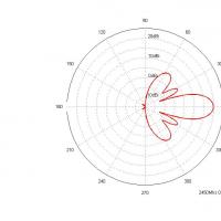
The radiation pattern for the antennas is reproduced in the form of lobes. The directivity of the antenna is determined by the width of the main lobe, and the immunity from interference is determined by the level of the side and rear lobes.
A similar homemade outdoor antenna, known as a "horn" (fan vibrator), was often used to receive broadcast signals not so long ago. In terms of parameters, it would be suitable for “digital”. But it is used only for receiving MV from channels 1 to 12. Using the same principle, you can make a UHF antenna.

The simplest design consists of metal plates in the form of isosceles triangles. The triangles need to be positioned so that their right angles are towards each other with a gap of about 1 cm. Along the hypotenuses, you need to strengthen two slats and install copper wires (enameled) of any diameter at a distance of 2-2.5 cm from each other. The width and height of the decimeter antenna are the same. When attaching the cable at a point with zero potential, it can be tied without soldering.
If you stretch such an antenna in the area of a window, one and a half meters wide, then it will receive a TV signal from any direction, without additional rotation. The disadvantage of the design is the low gain, and the SDC is completely zero. So in places with strong interference and a very weak signal, using an antenna is problematic.
Important. Sometimes radio amateurs try to make an omnidirectional antenna using a helix instead of a triangle, since it is smaller in size for similar frequencies. But it is more difficult to construct this type of UHF antenna with your own hands. Coordination with the cable also causes difficulties.
A type of all-wave antenna, easy to manufacture, allowing you to get a decent image. Well suited for use in environments with a strong but intermittent signal. The device is a classical dipole circuit. Due to their size, 0.5-liter aluminum cans are ideal for use as arms of a UHF vibrator. If you take jars of larger or smaller dimensions, the reception frequencies will change. The basis is the principle that when the diameter of the vibrator arms (linear) increases, the operating frequency range expands while maintaining other characteristics.
The simplest antenna of two cans is suitable as an indoor antenna for receiving an analog signal. The cable is not even subject to approval if its length is no more than two meters.

Sequencing:
- Attach a plug to one end of the cable to connect to the TV, strip the other by removing the insulating layer, 10 centimeters from the beginning. Untwist the cable cores, remove the foil;
- Attach the central core of the cable to one can, and the wires of the shielding braid to the other;
- Using adhesive tape or tape, install the cans on the insulating frame with the open part facing each other. This can be a wooden plank or a regular clothes hanger.
The distance between the banks is set to approximately 7-8 cm.
Important! It is necessary to ensure a tight fit of the wires to the metal of the can.
You can assemble a whole grid from cans, increasing the protection against interference with the help of a mesh screen installed at the back. This design is used outdoors and is mounted on a dielectric mast. The screen must also be connected to the mast using dielectric materials. If you make more than 4 crossbars, then difficulties will arise in matching the cable; 2 will not provide sufficient reinforcement. The distance between the crossbars is equal to half the average wavelength of the channels to which reception needs to be tuned. If you have an amplifier, it can be mounted additionally.
Another simple one. The goal is to obtain a circle-shaped frame capable of receiving a narrow range signal. An antenna for digital TV must have high immunity to interference. This design is also a selective filter that reduces interference. It works well inside apartments with reinforced concrete walls.

The disadvantage of this antenna is that the input impedance of the frame will be about 300 Ohms, and for the feeder the wave impedance will be 75 Ohms. It is necessary to install a matching device or make a frame with an input impedance of 75 Ohms. It has the shape of a rectangle (side length ratio 1:2). Both options are not very convenient. There is a third original solution - for the matching device, take the same cable and make a special loop out of it.
Based on the calculations, in the decimeter range for the ring you need to take a piece of coaxial cable 5.3 m, for a loop - 1.75 m

Making a loop antenna:
- Cut a piece of cable for the ring and for the loop;
- A part of the cable is bent into a ring and installed on plywood, plexiglass or other insulating material;
- A loop is made from another piece, the ends of which should be flush with the end of the cable going to the TV or receiver. Can be fixed with tape;
- The wires of the three shielding braids are connected to each other by soldering. The shield cores from the loop must be connected on both sides to the shielding cores of the ring. The central wire of the cable to the TV is with one side.
Note! The structure, placed outdoors, is protected from bad weather by a plastic casing.
Wave channel
The maximum gain, efficiency and interference protection for a self-made device is provided by a wave channel antenna. Suitable for use at a considerable distance from the broadcast center. In the city it is able to reduce interference, as it has precise directionality. The same property limits the number of received channels, since beyond the boundaries of the frequency selected for tuning, the antenna characteristics sharply decrease.

The antenna drawings represent a device that consists of shortened directors, or guides with capacitive reactance, an active vibrator and a reflector. The electromagnetic signal is oriented by the directors in the direction of the active vibrator. A longer reflector with inductive reactance located behind it reflects the waves passing by it to it.
Important! One reflector is enough, but there can be a different number of directors: up to 10 or more. With a larger number of directors, the gain increases, but the range of received frequencies decreases.

The television cable is connected to an active vibrator. Its relationship with the directors and reflector reduces its own wave resistance. The force of the fall depends on the gain. As a result, there is a mismatch with the television cable. For this reason, the active vibrator is made in the form of a loop, having an initial resistance of 300 Ohms. After interacting with several directors and a reflector, the resistance becomes 75 ohms. This ratio is valid for a five-element device.
For UHF, vibrators must be made of a metal tube from 6 to 10 mm in diameter. The total number of elements of the decimeter device is 16. All elements are connected to the boom actually at points with zero potential. This means that the material of the boom, like the mast, can be taken of any kind. For example, polypropylene pipes.
Important! The antenna must be strictly coordinated with the cable. A loop of coaxial cable can be used as a matching device.
In theory, the length of the loop is half the wavelength (the working wave is taken). But it is necessary to take into account the correction for cable insulation. When using 75 ohm coaxial cable, the loop size will be 0.35 of the wavelength. Inter-terminal distance – 6 cm.
Zigzag
Zigzag is a Kharchenko antenna circuit, refers to broadband devices. The design dimensions for the decimeter range are compact and easily allow it to be used indoors. It is especially effective in remote settlements when receiving in different directions. The limits of received frequencies while maintaining parameters overlap with a factor of 2.6-2.7.

The classic zigzag is difficult to manufacture and requires precise calculations. Widely used for receiving analogue television programs. For a digital signal, everything is greatly simplified.
Rhombus
The diamond design is a type of zigzag. The best material for the main circuit is copper tubes, another possible material is aluminum sheets (thickness 6 mm and above), cut into strips. To create a container, inserts made of tin, metal mesh or foil are used within the boundaries of small side rhombuses. A reflector is mounted at the back. Insert containers and a reflector complement the structure to increase sensitivity. If the signal is good, you can do without these elements.
Important! Mesh or tin inserts are soldered along the contour. This is not necessary when using thin metal sheets.
The coaxial cable should not be bent too much. It is brought to the side top of the diamond, and then directed to the center and soldered.
At the point with zero potential (the lower vertex of the diamond), an electrical connection must be made to the wires of the shielding braid.
Log-periodic
If the antenna does not always cope with an analog signal without adjustment, then it is ideal for receiving a digital television signal. It consists of a long rod to which halves of dipoles of different lengths are attached. The gaps between the vibrators and their length vary exponentially. Calculating an antenna is quite difficult. There are several methods presented on the Internet.

Features of a log periodic antenna:
- The central rod feeds the right and left vibrators separately. They must be in antiphase;
- The rod consists of two load-bearing members. Left-right vibrators take turns changing carriers. The first left is the upper carrier, the first right is the lower. The next row is the opposite;
- The number of vibrators is determined by the design of the antenna. The longest ones, located at the back, are equal in length to the length of a half-wave of the lower limit of the range;
- The coaxial cable is laid to the middle of the structure, passing inside one of the guides. At the exit from the nose, the central core must be connected to the second carrier. Such a line, consisting of two wires, will act as a balun transformer. There is another gasket option;
- For better matching, the line is short-circuited behind the longest vibrator (a distance of 1/8 of the wavelength of the lower limit of the range);
- The diameter of the tubes should be 10-15 mm for a decimeter wave.
- Thin cables will cause high attenuation, requiring a wire of at least 6mm in diameter. The cable is tied only from the inside, otherwise the quality of the antenna decreases.

- All structural elements with signal current flowing must be soldered or welded. This is especially true for outdoor antennas;
- Coaxial cables do not lend themselves well to conventional soldering, and prolonged heating can damage the cable. It is best to solder using low-melting solder, replacing rosin with flux paste.
There are the simplest options for making homemade antennas and more complex ones. Depending on knowledge and accumulated experience, each user can choose an option that is personally acceptable to him.
Video
Equipment for digital television is what you can buy in our store. Our company has been operating in the market of broadcast and satellite equipment since 2003 and we already know most of our clients by sight.
For regular customers of our online store there is a system of discounts, which are calculated automatically according to the coupon number assigned to you personally.
All equipment undergoes pre-sale preparation, namely, the latest version of software is installed on satellite and terrestrial set-top boxes. All receivers are tested for functionality.
Our company delivers equipment both in Moscow and throughout Russia. Most courier delivery companies have agreements on preferential delivery prices.
In our online store you can find almost any equipment that you may need to receive satellite and terrestrial television. We have tried to make the ordering process convenient for anyone. If you plan to order not one item, but several, then you can use the store search and pay attention to the accompanying equipment. If you want to pick up equipment for receiving satellite TV, then you should go to the tab menu “Satellite TV”, if to receive terrestrial or cable TV, then “Terrestrial TV”, etc. If you have questions during the ordering process, you can use the online chat, which is located on each page of the online store, or request a call back.
We hope that in the online digital TV store you can spend a minimum amount of time ordering the required equipment.
Once upon a time, a good television antenna was in short supply; purchased ones did not differ in quality and durability, to put it mildly. Making an antenna for a “box” or “coffin” (an old tube TV) with your own hands was considered a sign of skill. Interest in homemade antennas continues to this day. There is nothing strange here: the conditions for TV reception have changed dramatically, and manufacturers, believing that there is and will not be anything significantly new in the theory of antennas, most often adapt electronics to long-known designs, without thinking about the fact that The main thing for any antenna is its interaction with the signal on the air.
What has changed on air?
Firstly, almost the entire volume of TV broadcasting is currently carried out in the UHF range. First of all, for economic reasons, it greatly simplifies and reduces the cost of the antenna-feeder system of transmitting stations, and, more importantly, the need for its regular maintenance by highly qualified specialists engaged in hard, harmful and dangerous work.
Second - TV transmitters now cover almost all more or less populated areas with their signal, and a developed communication network ensures the delivery of programs to the most remote corners. There, broadcasting in the habitable zone is provided by low-power, unattended transmitters.
Third, the conditions for the propagation of radio waves in cities have changed. On the UHF, industrial interference leaks in weakly, but reinforced concrete high-rise buildings are good mirrors for them, repeatedly reflecting the signal until it is completely attenuated in an area of seemingly reliable reception.
Fourth - There are a lot of TV programs on air now, dozens and hundreds. How diverse and meaningful this set is is another question, but counting on receiving 1-2-3 channels is now pointless.
Finally, digital broadcasting has developed. The DVB T2 signal is a special thing. Where it still exceeds the noise even just a little, by 1.5-2 dB, the reception is excellent, as if nothing had happened. But a little further or to the side - no, it’s cut off. “Digital” is almost insensitive to interference, but if there is a mismatch with the cable or phase distortion anywhere in the path, from the camera to the tuner, the picture can crumble into squares even with a strong clean signal.
Antenna requirements
In accordance with the new reception conditions, the basic requirements for TV antennas have also changed:
- Its parameters such as the directivity coefficient (DAC) and the protective action coefficient (PAC) are now of no decisive importance: modern air is very dirty, and along the tiny side lobe of the directional pattern (DP), at least some interference will get through, and You need to fight it using electronic means.
- In return, the antenna's own gain (GA) becomes especially important. An antenna that catches the air well, rather than looking at it through a small hole, will provide a reserve of power for the received signal, allowing the electronics to clear it of noise and interference.
- A modern television antenna, with rare exceptions, must be a range antenna, i.e. its electrical parameters must be preserved naturally, at the level of theory, and not squeezed into acceptable limits through engineering tricks.
- The TV antenna must be matched with the cable over its entire operating frequency range without additional matching and balancing devices (MCD).
- The amplitude-frequency response of the antenna (AFC) should be as smooth as possible. Sharp surges and dips are certainly accompanied by phase distortions.
The last 3 points are determined by the requirements for receiving digital signals. Customized, i.e. Working theoretically at the same frequency, antennas can be “stretched” in frequency, for example. antennas of the “wave channel” type on the UHF with an acceptable signal-to-noise ratio capture channels 21-40. But their coordination with the feeder requires the use of USSs, which either strongly absorb the signal (ferrite) or spoil the phase response at the edges of the range (tuned). And such an antenna, which works perfectly on analogue, will receive “digital” poorly.
In this regard, from all the great variety of antennas, this article will consider TV antennas, available for self-production, of the following types:
- Frequency independent (all-wave)– does not have high parameters, but is very simple and cheap, it can be done in literally an hour. Outside the city, where the airwaves are cleaner, it will be able to receive digital or a fairly powerful analogue not a short distance from the television center.
- Range log-periodic. Figuratively speaking, it can be likened to a fishing trawl, which sorts the prey during fishing. It is also quite simple, fits perfectly with the feeder throughout its entire range, and does not change its parameters at all. The technical parameters are average, so it is more suitable for a summer residence, and in the city as a room.
- Several modifications of the zigzag antenna, or Z-antennas. In the MV range, this is a very solid design that requires considerable skill and time. But on the UHF, due to the principle of geometric similarity (see below), it is so simplified and shrunk that it can well be used as a highly efficient indoor antenna under almost any reception conditions.
Note: The Z-antenna, to use the previous analogy, is a frequent flyer that scoops up everything in the water. As the air became littered, it fell out of use, but with the development of digital TV, it was once again on the high horse - throughout its entire range, it is just as perfectly coordinated and keeps the parameters as a “speech therapist.”
Precise matching and balancing of almost all antennas described below is achieved by laying the cable through the so-called. zero potential point. It has special requirements, which will be discussed in more detail below.
About vibrator antennas
In the frequency band of one analog channel, up to several dozen digital ones can be transmitted. And, as already said, the digital works with an insignificant signal-to-noise ratio. Therefore, in places very remote from the television center, where the signal of one or two channels barely reaches, the good old wave channel (AVK, wave channel antenna), from the class of vibrator antennas, can be used for receiving digital TV, so at the end we will devote a few lines and to her.
About satellite reception
There is no point in making a satellite dish yourself. You still need to buy a head and a tuner, and behind the external simplicity of the mirror lies a parabolic surface of oblique incidence, which not every industrial enterprise can produce with the required accuracy. The only thing homemade people can do is set up a satellite dish, about that.
About antenna parameters
Accurate determination of the antenna parameters mentioned above requires knowledge of higher mathematics and electrodynamics, but it is necessary to understand their meaning when starting to manufacture an antenna. Therefore, we will give somewhat rough, but still clarifying definitions (see figure on the right):

- KU is the ratio of the signal power received by the antenna on the main (main) lobe of its DP to its same power received in the same place and at the same frequency by an omnidirectional, circular, DP antenna.
- KND is the ratio of the solid angle of the entire sphere to the solid angle of the opening of the main lobe of the DN, assuming that its cross-section is a circle. If the main petal has different sizes in different planes, you need to compare the area of the sphere and its cross-sectional area of the main petal.
- SCR is the ratio of the signal power received at the main lobe to the sum of the interference powers at the same frequency received by all secondary (back and side) lobes.
Notes:
- If the antenna is a band antenna, the powers are calculated at the frequency of the useful signal.
- Since there are no completely omnidirectional antennas, a half-wave linear dipole oriented in the direction of the electric field vector (according to its polarization) is taken as such. Its QU is considered equal to 1. TV programs are transmitted with horizontal polarization.
It should be remembered that CG and KNI are not necessarily interrelated. There are antennas (for example, “spy” - single-wire traveling wave antenna, ABC) with high directivity, but single or lower gain. These look into the distance as if through a diopter sight. On the other hand, there are antennas, e.g. Z-antenna, which combines low directivity with significant gain.
About the intricacies of manufacturing
All antenna elements through which useful signal currents flow (specifically, in the descriptions of individual antennas) must be connected to each other by soldering or welding. In any prefabricated unit in the open air, the electrical contact will soon be broken, and the parameters of the antenna will deteriorate sharply, up to its complete unusability.
This is especially true for points of zero potential. In them, as experts say, there is a voltage node and a current antinode, i.e. its greatest value. Current at zero voltage? Nothing surprising. Electrodynamics has moved as far from Ohm's law on direct current as the T-50 has gone from a kite.
Places with zero potential points for digital antennas are best made bent from solid metal. A small “creeping” current in welding when receiving the analogue in the picture will most likely not affect it. But, if a digital signal is received at the noise level, then the tuner may not see the signal due to the “creep”. Which, with pure current at the antinode, would give stable reception.
About cable soldering
The braid (and often the central core) of modern coaxial cables is made not of copper, but of corrosion-resistant and inexpensive alloys. They solder poorly and if you heat them for a long time, you can burn out the cable. Therefore, you need to solder the cables with a 40-W soldering iron, low-melting solder and with flux paste instead of rosin or alcohol rosin. There is no need to spare the paste; the solder immediately spreads along the veins of the braid only under a layer of boiling flux.

Types of antennas
All-wave
An all-wave (more precisely, frequency-independent, FNA) antenna is shown in Fig. It consists of two triangular metal plates, two wooden slats, and a lot of enameled copper wires. The diameter of the wire does not matter, and the distance between the ends of the wires on the slats is 20-30 mm. The gap between the plates to which the other ends of the wires are soldered is 10 mm.
Note: Instead of two metal plates, it is better to take a square of one-sided foil fiberglass with triangles cut into copper.
The width of the antenna is equal to its height, the opening angle of the blades is 90 degrees. The cable routing diagram is shown there in Fig. The point marked in yellow is the point of quasi-zero potential. There is no need to solder the cable braid to the fabric in it, just tie it tightly, and the capacity between the braid and the fabric will be enough for matching.
The CHNA, stretched in a window 1.5 m wide, receives all meter and DCM channels from almost all directions, except for a dip of about 15 degrees in the plane of the canvas. This is its advantage in places where it is possible to receive signals from different television centers; it does not need to be rotated. Disadvantages - single gain and zero gain, therefore, in the interference zone and outside the zone of reliable reception, the CNA is not suitable.
Note : There are other types of CNA, for example. in the form of a two-turn logarithmic spiral. It is more compact than the CNA made of triangular sheets in the same frequency range, therefore it is sometimes used in technology. But in everyday life this does not provide any advantages, it is more difficult to make a spiral CNA, and it is more difficult to coordinate with a coaxial cable, so we are not considering it.
Based on the CHNA, the once very popular fan vibrator (horns, flyer, slingshot) was created, see fig. Its directivity factor and coefficient of performance are something around 1.4 with a fairly smooth frequency response and linear phase response, so it would be suitable for digital use even now. But - it works only on HF (channels 1-12), and digital broadcasting is on UHF. However, in the countryside, with an elevation of 10-12 m, it may be suitable for receiving an analogue. Mast 2 can be made of any material, but fastening strips 1 are made of a good non-wetting dielectric: fiberglass or fluoroplastic with a thickness of at least 10 mm.

Beer all-wave

The all-wave antenna made from beer cans is clearly not the fruit of the hangover hallucinations of a drunken radio amateur. This is truly a very good antenna for all reception situations, you just need to do it right. And it’s extremely simple.
Its design is based on the following phenomenon: if you increase the diameter of the arms of a conventional linear vibrator, then its operating frequency band expands, but other parameters remain unchanged. In long-distance radio communications, since the 20s, the so-called Nadenenko's dipole based on this principle. And beer cans are just the right size to serve as the arms of a vibrator on the UHF. In essence, the CHNA is a dipole, the arms of which expand indefinitely to infinity.
The simplest beer vibrator made of two cans is suitable for indoor analogue reception in the city, even without coordination with the cable, if its length is no more than 2 m, on the left in Fig. And if you assemble a vertical in-phase array from beer dipoles with a step of half a wave (on the right in the figure), match it and balance it using an amplifier from a Polish antenna (we will talk about it later), then thanks to the vertical compression of the main lobe of the pattern, such an antenna will give good CU.
The gain of the “tavern” can be further increased by adding a CPD at the same time, if a mesh screen is placed behind it at a distance equal to half the grid pitch. The beer grill is mounted on a dielectric mast; The mechanical connections between the screen and the mast are also dielectric. The rest is clear from the following. rice.

Note: the optimal number of lattice floors is 3-4. With 2, the gain in gain will be small, and more is difficult to coordinate with the cable.
Video: making a simple antenna from beer cans
"Speech therapist"
A log-periodic antenna (LPA) is a collecting line to which halves of linear dipoles (i.e., pieces of conductor a quarter of the operating wavelength) are alternately connected, the length and distance between which vary in geometric progression with an index less than 1, in the center in Fig. The line can be either configured (with a short circuit at the end opposite to the cable connection) or free. An LPA on a free (unconfigured) line is preferable for digital reception: it comes out longer, but its frequency response and phase response are smooth, and the matching with the cable does not depend on frequency, so we will focus on it.

The LPA can be manufactured for any predetermined frequency range, up to 1-2 GHz. When the operating frequency changes, its active region of 1-5 dipoles moves back and forth along the canvas. Therefore, the closer the progression indicator is to 1, and accordingly the smaller the antenna opening angle, the greater the gain it will give, but at the same time its length increases. At UHF, 26 dB can be achieved from an outdoor LPA, and 12 dB from a room LPA.
LPA can be said to be an ideal digital antenna based on its totality of qualities, so let’s look at its calculation in a little more detail. The main thing you need to know is that an increase in the progression indicator (tau in the figure) gives an increase in gain, and a decrease in the LPA opening angle (alpha) increases the directivity. A screen is not needed for the LPA; it has almost no effect on its parameters.
Calculation of digital LPA has the following features:
- They start it, for the sake of frequency reserve, with the second longest vibrator.
- Then, taking the reciprocal of the progression index, the longest dipole is calculated.
- After the shortest dipole based on the given frequency range, another one is added.
Let's explain with an example. Let's say our digital programs are in the range of 21-31 TVK, i.e. at 470-558 MHz in frequency; wavelengths, respectively, are 638-537 mm. Let’s also assume that we need to receive a weak noisy signal far from the station, so we take the maximum (0.9) progression rate and the minimum (30 degrees) opening angle. For the calculation, you will need half the opening angle, i.e. 15 degrees in our case. The opening can be further reduced, but the length of the antenna will increase exorbitantly, in cotangent terms.
We consider B2 in Fig: 638/2 = 319 mm, and the arms of the dipole will be 160 mm each, you can round up to 1 mm. The calculation will need to be carried out until you get Bn = 537/2 = 269 mm, and then calculate another dipole.
Now we consider A2 as B2/tg15 = 319/0.26795 = 1190 mm. Then, through the progression indicator, A1 and B1: A1 = A2/0.9 = 1322 mm; B1 = 319/0.9 = 354.5 = 355 mm. Next, sequentially, starting with B2 and A2, we multiply by the indicator until we reach 269 mm:
- B3 = B2*0.9 = 287 mm; A3 = A2*0.9 = 1071 mm.
- B4 = 258 mm; A4 = 964 mm.
Stop, we are already less than 269 mm. We check whether we can meet the gain requirements, although it is clear that we can’t: to get 12 dB or more, the distances between the dipoles should not exceed 0.1-0.12 wavelengths. In this case, for B1 we have A1-A2 = 1322 – 1190 = 132 mm, which is 132/638 = 0.21 wavelengths of B1. We need to “pull up” the indicator to 1, to 0.93-0.97, so we try different ones until the first difference A1-A2 is reduced by half or more. For a maximum of 26 dB, you need a distance between dipoles of 0.03-0.05 wavelengths, but not less than 2 dipole diameters, 3-10 mm at UHF.
Note: cut off the rest of the line behind the shortest dipole; it is needed only for calculations. Therefore, the actual length of the finished antenna will be only about 400 mm. If our LPA is external, this is very good: we can reduce the opening, obtaining greater directionality and protection from interference.
Video: antenna for digital TV DVB T2
About the line and the mast
The diameter of the tubes of the LPA line on the UHF is 8-15 mm; the distance between their axes is 3-4 diameters. Let’s also take into account that thin “lace” cables give such attenuation per meter on the UHF that all antenna-amplification tricks will come to naught. You need to take a good coaxial for an outdoor antenna, with a shell diameter of 6-8 mm. That is, the tubes for the line must be thin-walled, seamless. You cannot tie the cable to the line from the outside; the quality of the LPA will drop sharply.
It is necessary, of course, to attach the outer propulsion boat to the mast by the center of gravity, otherwise the small windage of the propulsion craft will turn into a huge and shaking one. But it is also impossible to connect a metal mast directly to the line: you need to provide a dielectric insert of at least 1.5 m in length. The quality of the dielectric does not play a big role here; oiled and painted wood will do.
About the Delta antenna
If the UHF LPA is consistent with the cable amplifier (see below, about Polish antennas), then the arms of a meter dipole, linear or fan-shaped, like a “slingshot”, can be attached to the line. Then we will get a universal VHF-UHF antenna of excellent quality. This solution is used in the popular Delta antenna, see fig.

Delta antenna
Zigzag on air
A Z-antenna with a reflector gives the same gain and gain as the LPA, but its main lobe is more than twice as wide horizontally. This can be important in rural areas when there is TV reception from different directions. And the decimeter Z-antenna has small dimensions, which is essential for indoor reception. But its operating range is theoretically not unlimited; frequency overlap while maintaining parameters acceptable for the digital range is up to 2.7.

The design of the MV Z-antenna is shown in Fig; The cable route is highlighted in red. There in the lower left there is a more compact ring version, colloquially known as a “spider”. It clearly shows that the Z-antenna was born as a combination of a CNA with a range vibrator; There is also something of a rhombic antenna in it, which does not fit into the theme. Yes, the “spider” ring does not have to be wooden, it can be a metal hoop. "Spider" receives 1-12 MV channels; The pattern without a reflector is almost circular.
The classic zigzag works either on 1-5 or 6-12 channels, but for its manufacture you only need wooden slats, enameled copper wire with d = 0.6-1.2 mm and several scraps of foil fiberglass, so we give the dimensions in fraction for 1-5/6-12 channels: A = 3400/950 mm, B, C = 1700/450 mm, b = 100/28 mm, B = 300/100 mm. At point E there is zero potential; here you need to solder the braid to a metallized support plate. Reflector dimensions, also 1-5/6-12: A = 620/175 mm, B = 300/130 mm, D = 3200/900 mm.
The range Z-antenna with a reflector gives a gain of 12 dB, tuned to one channel - 26 dB. To build a single-channel one based on a range zigzag, you need to take the side of the square of the canvas in the middle of its width at a quarter of the wavelength and recalculate all other dimensions proportionally.
Folk Zigzag
As you can see, the MV Z-antenna is a rather complex structure. But its principle shows itself in all its glory on the UHF. The UHF Z-antenna with capacitive inserts, combining the advantages of the “classics” and the “spider”, is so easy to make that even in the USSR it earned the title of folk antenna, see fig.

Material – copper tube or aluminum sheet with a thickness of 6 mm. The side squares are solid metal or covered with mesh, or covered with a tin. In the last two cases, they need to be soldered along the circuit. The coax cannot be bent sharply, so we guide it so that it reaches the side corner, and then does not go beyond the capacitive insert (side square). At point A (zero potential point), we electrically connect the cable braid to the fabric.
Note: aluminum cannot be soldered with conventional solders and fluxes, so “folk” aluminum is suitable for outdoor installation only after sealing the electrical connections with silicone, since everything in it is screwed.
Video: example of a double triangle antenna
Wave channel

The wave channel antenna (AWC), or Udo-Yagi antenna, available for self-production, is capable of giving the highest gain, directivity factor and efficiency factor. But it can only receive digital signals on UHF on 1 or 2-3 adjacent channels, because belongs to the class of highly tuned antennas. Its parameters deteriorate sharply beyond the tuning frequency. It is recommended to use AVK under very poor reception conditions, and make a separate one for each TVK. Fortunately, this is not very difficult - AVK is simple and cheap.
The operation of the AVK is based on “raking” the electromagnetic field (EMF) of the signal to the active vibrator. Externally small, lightweight, with minimal windage, the AVK can have an effective aperture of dozens of wavelengths of the operating frequency. Directors (directors) that are shortened and therefore have capacitive impedance (impedance) direct the EMF to the active vibrator, and the reflector (reflector), elongated, with inductive impedance, throws back to it what has slipped past. Only 1 reflector is needed in an AVK, but there can be from 1 to 20 or more directors. The more there are, the higher the gain of the AVC, but the narrower its frequency band.
From interaction with the reflector and directors, the wave impedance of the active (from which the signal is taken) vibrator drops the more, the closer the antenna is tuned to the maximum gain, and coordination with the cable is lost. Therefore, the active dipole AVK is made into a loop, its initial wave impedance is not 73 Ohms, like a linear one, but 300 Ohms. At the cost of reducing it to 75 Ohms, an AVK with three directors (five-element, see the figure on the right) can be adjusted to almost a maximum gain of 26 dB. A characteristic pattern for AVK in the horizontal plane is shown in Fig. at the beginning of the article.
AVK elements are connected to the boom at points of zero potential, so the mast and boom can be anything. Propylene pipes work very well.
Calculation and adjustment of AVK for analog and digital are somewhat different. For analogue, the wave channel must be calculated at the carrier frequency of the image Fi, and for digital – at the middle of the TVC spectrum Fc. Why this is so - unfortunately, there is no room to explain here. For the 21st TVC Fi = 471.25 MHz; Fс = 474 MHz. UHF TVCs are located close to each other at 8 MHz, so their tuning frequencies for AVK are calculated simply: Fn = Fi/Fс(21 TVC) + 8(N – 21), where N is the number of the desired channel. Eg. for 39 TVCs Fi = 615.25 MHz, and Fc = 610 MHz.
In order not to write down a lot of numbers, it is convenient to express the dimensions of the AVK in fractions of the operating wavelength (it is calculated as A = 300/F, MHz). The wavelength is usually denoted by the small Greek letter lambda, but since there is no default Greek alphabet on the Internet, we will conventionally denote it by the large Russian L.
The dimensions of the digitally optimized AVK, according to the figure, are as follows:

- P = 0.52L.
- B = 0.49L.
- D1 = 0.46L.
- D2 = 0.44L.
- D3 = 0.43l.
- a = 0.18L.
- b = 0.12L.
- c = d = 0.1L.
If you don’t need a lot of gain, but reducing the size of the AVK is more important, then D2 and D3 can be removed. All vibrators are made of a tube or rod with a diameter of 30-40 mm for 1-5 TVKs, 16-20 mm for 6-12 TVKs and 10-12 mm for UHF.
AVK requires precise coordination with the cable. It is the careless implementation of the matching and balancing device (CMD) that explains most of the failures of amateurs. The simplest USS for AVK is a U-loop made from the same coaxial cable. Its design is clear from Fig. on right. The distance between signal terminals 1-1 is 140 mm for 1-5 TVKs, 90 mm for 6-12 TVKs and 60 mm for UHF.
Theoretically, the length of the knee l should be half the length of the working wave, and this is what is indicated in most publications on the Internet. But the EMF in the U-loop is concentrated inside the cable filled with insulation, so it is necessary (for numbers - especially mandatory) to take into account its shortening factor. For 75-ohm coaxials it ranges from 1.41-1.51, i.e. l you need to take from 0.355 to 0.330 wavelengths, and take exactly so that the AVK is an AVK, and not a set of pieces of iron. The exact value of the shortening factor is always in the cable certificate.
Recently, the domestic industry has begun to produce reconfigurable AVK for digital, see Fig. The idea, I must say, is excellent: by moving the elements along the boom, you can fine-tune the antenna to local reception conditions. It is better, of course, for a specialist to do this - the element-by-element adjustment of the AVC is interdependent, and an amateur will certainly get confused.

About “Poles” and amplifiers
Many users have Polish antennas, which previously received analogue decently, but refuse to accept digital - they break or even disappear completely. The reason, I beg your pardon, is the obscene commercial approach to electrodynamics. Sometimes I feel ashamed for my colleagues who have concocted such a “miracle”: the frequency response and phase response resemble either a psoriasis hedgehog or a horse’s comb with broken teeth.
The only good thing about the Poles is their antenna amplifiers. Actually, they do not allow these products to die ingloriously. Belt amplifiers are, firstly, low-noise, broadband. And, more importantly, with a high-impedance input. This allows, at the same strength of the EMF signal on the air, to supply several times more power to the tuner input, which makes it possible for the electronics to “rip out” a number from very ugly noise. In addition, due to the high input impedance, the Polish amplifier is an ideal USS for any antennas: whatever you attach to the input, the output is exactly 75 Ohms without reflection or creep.
However, with a very poor signal, outside the zone of reliable reception, the Polish amplifier no longer works. Power is supplied to it via a cable, and power decoupling takes away 2-3 dB of the signal-to-noise ratio, which may not be enough for the digital signal to go right into the outback. Here you need a good TV signal amplifier with separate power supply. It will most likely be located near the tuner, and the control system for the antenna, if required, will have to be made separately.

The circuit of such an amplifier, which has shown almost 100% repeatability even when implemented by novice radio amateurs, is shown in Fig. Gain adjustment – potentiometer P1. The decoupling chokes L3 and L4 are standard purchased ones. Coils L1 and L2 are made according to the dimensions in the wiring diagram on the right. They are part of signal bandpass filters, so small deviations in their inductance are not critical.
However, the installation topology (configuration) must be observed exactly! And in the same way, a metal shield is required, separating the output circuits from the other circuit.
Where to begin?
We hope that experienced craftsmen will find some useful information in this article. And for beginners who don’t yet feel the air, it’s best to start with a beer antenna. The author of the article, by no means an amateur in this field, was quite surprised at one time: the simplest “pub” with ferrite matching, as it turned out, takes the MV no worse than the proven “slingshot”. And what it costs to do both - see the text.
(2
ratings, average: 4,00
out of 5)
Senya said:
Did I miss something? In calculating LPA B2, we divide by tanges 15. B is a dipole (i.e., two half arms). The opening angle is set to 30, and 15 is half the opening angle. Tangent is the ratio of opposite to adjacent. If we take the entire dipole (320 in the example), then it forms an isosceles triangle with an angle of 30 and trigonometry is not applicable here. However, if you take half the angle, you will have a right triangle, with an angle of 15 and the opposite leg B2/2. then we can count the adjacent side A2. I think so…
Said):
And on the roof there was a satisfactory reception for Polyachka. I’m 70-80 kilometers from the television center. These are the problems I have. From the balcony you can catch 3-4 pieces from 30 channels, and then with “cubes”. Sometimes I watch TV channels from the Internet on the computer in my room, but my wife cannot watch her favorite channels normally on her TV. Neighbors advise installing cable, but you have to pay for it every month, and I already pay for the Internet, and my pension is not flexible. We keep pulling and pulling and there’s not enough for everything.
Pyotr Kopitonenko said:
It’s not possible to install an antenna on the roof of the house; the neighbors swear that I walk around and break the roofing material covering and then their ceiling leaks. Actually, I am very “grateful” to that economist who received a prize for saving money. He came up with the idea of removing the expensive gable roof from the houses and replacing it with a flat roof covered with poor roofing material. The economist received money for saving, and the people on the top floors now suffer all their lives. Water flows on their heads and on their beds. They change the roofing felt every year, but it becomes unusable within a season. In frosty weather, it cracks and rainwater and snow flow into the apartment, even if no one walks on the roof!!!
Sergey said:
Greetings!
Thanks for the article, who is the author (I don’t see the signature)?
The LPA works perfectly according to the above method, UHF channels 30 and 58. Tested in the city (reflected signal) and outside the city, distances to the transmitter (1 kW) respectively: 2 and 12 km approximately. Practice has shown that there is no urgent need for the “B1” dipole, but another dipole before the shortest one has a significant effect, judging by the signal intensity in %. Especially in city conditions, where you need to catch (in my case) the reflected signal. Only I made an antenna with a “short circuit”, it happened that way, there was simply no suitable insulator.
In general, I recommend it.
Vasily said:
IMHO: people looking for an antenna to receive digital TV, forget about the LPA. These wide-range antennas were created in the second half of the 50s (!!) of the last century in order to catch foreign television centers while on the shores of the Soviet Baltic states. In magazines of the time, this was bashfully called “extra-long-range reception.” Well, we really loved watching Swedish porn at night on the Riga seaside...
In terms of purpose, I can say the same about “double, triple, etc. squares”, as well as any “zigzags”.
Compared to a “wave channel” of similar range and gain, LPAs are more bulky and material-intensive. Calculating the LPA is complex, intricate and more like fortune telling and adjusting the results.
If in your region ECTV is broadcast on neighboring UHF channels (I have 37-38), then the best solution is to find a book online: Kapchinsky L.M. Television antennas (2nd edition, 1979) and make a “wave channel” for a group of UHF channels (if you broadcast above 21-41 channels, you will have to recalculate) described on page 67 et seq. (Fig. 39, Table 11).
If the transmitter is 15 - 30 km away, the antenna can be simplified by making it four - five element, simply without installing directors D, E and Zh.
For very close transmitters, I recommend indoor antennas; by the way, in the same book on pp. 106 - 109 there are drawings of wide-range indoor “wave channel” and LPA. The “wave channel” is visually smaller, simpler and sleeker with higher gain!
By clicking the “Add comment” button, I agree with the site.
Buying a good antenna for your dacha is not always advisable. Especially if she is visited from time to time. The point is not so much the cost, but the fact that after a while it may not be there. Therefore, many people prefer to make an antenna for their dacha themselves. Costs are minimal, quality is good. And the most important point is that a TV antenna can be made with your own hands in half an hour or an hour and then, if necessary, can be easily repeated...
Digital television in the DVB-T2 format is transmitted in the UHF range, and there is either a digital signal or it is not. If the signal is received, the picture is of good quality. Due to this. Any decimeter antenna is suitable for receiving digital television. Many radio amateurs are familiar with the TV antenna, which is called “zigzag” or “figure eight”. This DIY TV antenna can be assembled literally in a matter of minutes.
To reduce the amount of interference, a reflector is placed behind the antenna. The distance between the antenna and the reflector is selected experimentally - according to the “purity” of the picture  You can attach foil to the glass and get a good signal...
  Copper tube or wire is the best option; it bends well and is easy to bend.
It is very simple to make; the material is any conductive metal: tube, rod, wire, strip, corner. Despite its simplicity, she accepts it well. It looks like two squares (rhombuses) connected to each other. In the original, there is a reflector behind the square for more reliable signal reception. But it is more needed for analog signals. To receive digital television, you can do without it or install it later if the reception is too weak.
Materials
Copper or aluminum wire with a diameter of 2-5 mm is optimal for this homemade TV antenna. In this case, everything can be done in literally an hour. You can also use a tube, a corner, a strip of copper or aluminum, but you will need some kind of device to bend the frames to the desired shape. The wire can be bent with a hammer, securing it in a vice.

You will also need a coaxial antenna cable of the required length, a plug suitable for the connector on your TV, and some kind of mount for the antenna itself. The cable can be taken with a resistance of 75 Ohms and 50 Ohms (the second option is worse). If you are making a TV antenna with your own hands for installation outdoors, pay attention to the quality of the insulation.
The mounting depends on where you are going to hang your homemade antenna for digital television. On the upper floors, you can try to use it as a home decoration and hang it on curtains. Then you need large pins. At the dacha or if you take a homemade TV antenna to the roof, you will need to attach it to a pole. For this case, look for suitable fasteners. To work, you will also need a soldering iron, sandpaper and/or file, and a needle file.
Do you need a calculation?
To receive a digital signal, there is no need to count the wavelength. It is simply advisable to make the antenna more broadband in order to receive as many signals as possible. To do this, some changes were made to the original design (pictured above) (further in the text).
If you wish, you can make a calculation. To do this, you need to find out what wavelength the signal is broadcast on, divide by 4 and get the required side of the square. To obtain the required distance between the two parts of the antenna, make the outer sides of the diamonds slightly longer and the inner ones shorter.

Drawing of a figure-of-eight antenna for receiving digital TV
- The length of the “inner” side of the rectangle (B2) is 13 cm,
- “external” (B1) - 14 cm.
Due to the difference in lengths, a distance is formed between the squares (they should not be connected). The two extreme sections are made 1 cm longer so that you can fold the loop to which the coaxial antenna cable is soldered.
Making a frame
If you count all the lengths, you get 112 cm. Cut off the wire or whatever material you have, take pliers and a ruler, and start bending. The angles should be 90° or so. You can make a little mistake with the lengths of the sides - this is not fatal. It turns out like this:
- The first section is 13 cm + 1 cm per loop. The loop can be bent immediately.
- Two sections of 14 cm each.
- Two 13 cm each, but with a turn in the opposite direction - this is the point of inflection onto the second square.
- Again two 14 cm each.
- The last one is 13 cm + 1 cm per loop.
The antenna frame itself is ready. If everything was done correctly, there will be a distance of 1.5-2 cm between the two halves in the middle. There may be small discrepancies. Next, we clean the loops and the bend point to bare metal (treat it with fine-grain sandpaper), and tin it. Connect the two loops and crimp them with pliers to hold them tightly.

Cable preparation
We take the antenna cable and carefully clean it. How to do this is shown in the step-by-step photo. You need to strip the cable on both sides. One edge will be attached to the antenna. Here we strip it so that the wire sticks out 2 cm. If it turns out more, the excess (later) can be cut off. Twist the screen (foil) and braid into a bundle. It turned out to be two conductors. One is the central monocore of the cable, the second is twisted from many braided wires. Both are needed and need to be tinned.

We solder the plug to the second edge. A length of 1 cm or so is sufficient here. Also form two conductors and tin them.
Wipe the plug in the places where we will solder with alcohol or solvent, and clean it with emery (you can use a needle file). Place the plastic part of the plug on the cable, now you can start soldering. We solder a monocore to the central output of the plug, and a multicore twist to the side output. The last thing is to crimp the grip around the insulation.

Then you can simply screw on the plastic tip and fill it with glue or non-conductive sealant (this is important). While the glue/sealant has not hardened, quickly assemble the plug (screw on the plastic part) and remove the excess compound. So the plug will be almost eternal.
DIY DVB-T2 TV antenna: assembly
Now all that remains is to connect the cable and the frame. Since we were not tied to a specific channel, we will solder the cable to the middle point. This will increase the broadband of the antenna - more channels will be received. Therefore, we solder the second cut end of the cable to the two sides in the middle (those that were stripped and tinned). Another difference from the “original version” is that the cable does not need to be routed around the frame and soldered at the bottom. This will also expand the reception range.
The assembled antenna can be checked. If the reception is normal, you can finish the assembly - fill the solder joints with sealant. If the reception is poor, try first to find a place where the fishing is better. If there are no positive changes, you can try replacing the cable. To simplify the experiment, you can use regular telephone noodles. It costs a penny. Solder the plug and frame to it. Try it with her. If it catches better, it’s a bad cable. In principle, you can work on “noodles”, but not for long - they will quickly become unusable. It is better, of course, to install a normal antenna cable.

To protect the junction of the cable and the antenna frame from atmospheric influences, the soldering points can be wrapped with ordinary electrical tape. But this method is unreliable. If you remember, you can put on several heat-shrinkable tubes before soldering to insulate them. But the most reliable way is to fill everything with glue or sealant (they should not conduct current). As a “case” you can use lids for 5-6 liter water cylinders, ordinary plastic lids for jars, etc. We make indentations in the right places - so that the frame “sits” in them, do not forget about the cable outlet. Fill it with a sealing compound and wait until it sets. That's it, your DIY TV antenna for receiving digital television is ready.
Homemade double and triple square antenna
This is a narrowband antenna, which is used if you need to receive a weak signal. It can even help if a weaker signal is “clogged” by a stronger one. The only drawback is that you need precise orientation to the source. The same design can be made to receive digital television.
 You can also make five frames - for a more confident reception
  It is not advisable to paint or varnish - reception deteriorates. This is only possible in close proximity to the transmitter
The advantages of this design are that reception will be reliable even at a considerable distance from the repeater. You just need to specifically find out the broadcast frequency and maintain the dimensions of the frames and matching device.
Construction and materials
It is made from tubes or wire:
- 1-5 TV channel MV range - tubes (copper, brass, aluminum) with a diameter of 10-20 mm;
- 6-12 TV channel MV range - tubes (copper, brass, aluminum) 8-15 mm;
- UHF range - copper or brass wire with a diameter of 3-6 mm.
The double square antenna consists of two frames connected by two arrows - upper and lower. The smaller frame is a vibrator, the larger one is a reflector. An antenna consisting of three frames gives a higher gain. The third, smallest square is called the director.

The upper boom connects the middle of the frames and can be made of metal. The lower one is made of insulating material (textolite, gettinax, wooden plank). The frames must be installed so that their centers (the points of intersection of the diagonals) are on the same straight line. And this straight line should be directed towards the transmitter.
The active frame - the vibrator - has an open circuit. Its ends are screwed to a textolite plate measuring 30*60 mm. If the frames are made from a tube, the edges are flattened, holes are made in them and the lower arrow is attached through them.
The mast for this antenna must be wooden. At least the upper part of it. Moreover, the wooden part should start at a distance of at least 1.5 meters from the level of the antenna frames.
Dimensions
All dimensions for making this TV antenna with your own hands are given in the tables. The first table is for the meter range, the second is for the decimeter range.

In three-frame antennas, the distance between the ends of the vibrator (middle) frame is larger - 50 mm. Other sizes are given in the tables.

Connecting an active frame (vibrator) via a short-circuited cable
Since the frame is a symmetrical device, and it must be connected to an asymmetrical coaxial antenna cable, a matching device is required. In this case, a balancing short-circuited loop is usually used. It is made from pieces of antenna cable. The right segment is called the “loop”, the left one is called the “feeder”. A cable is attached to the junction of the feeder and the cable, which goes to the TV. The length of the segments is selected based on the wavelength of the received signal (see table).

A short piece of wire (loop) is cut at one end by removing the aluminum screen and twisting the braid into a tight bundle. Its central conductor can be cut down to insulation, since it does not matter. The feeder is also cut. Here, too, the aluminum screen is removed and the braid is twisted into a bundle, but the central conductor remains.
Further assembly proceeds like this:
- The braid of the cable and the central conductor of the feeder are soldered to the left end of the active frame (vibrator).
- The feeder braid is soldered to the right end of the vibrator.
- The lower end of the cable (braid) is connected to the feeder braid using a rigid metal jumper (you can use wire, just make sure there is good contact with the braid). In addition to the electrical connection, it also sets the distance between sections of the matching device. Instead of a metal jumper, you can twist the braid of the lower part of the cable into a bundle (remove the insulation in this area, remove the screen, roll it into a bundle). To ensure good contact, solder the bundles together with low-melting solder.
- The cable pieces must be parallel. The distance between them is about 50 mm (some deviations are possible). To fix the distance, clamps made of dielectric material are used. You can also attach a matching device to a textolite plate, for example.
- The cable going to the TV is soldered to the bottom of the feeder. Braid is connected to braid, center conductor to center conductor. To reduce the number of connections, the feeder and cable to the TV can be made single. Only in the place where the feeder should end must the insulation be removed so that the jumper can be installed.
This matching device allows you to get rid of noise, blurred contours, and a second blurry image. It is especially useful at a great distance from the transmitter, when the signal is clogged with interference.
Another variation of the triple square
In order not to connect a short-circuited loop, the triple square antenna vibrator is made elongated. In this case, you can connect the cable directly to the frame as shown in the figure. Only the height at which the antenna wire is soldered is determined in each case individually. After the antenna is assembled, “testing” is carried out. The cable is connected to the TV, the central conductor and braid are moved up/down, achieving a better image. In the position where the picture will be clearest, the antenna cable branches are soldered, and the soldering points are insulated. The position can be any - from the bottom jumper to the transition point to the frame.

Sometimes one antenna does not give the desired effect. The signal turns out to be a weak image - black and white. In this case, the standard solution is to install a television signal amplifier.
The simplest antenna for a summer residence is made from metal cans
To make this television antenna, in addition to the cable, you will only need two aluminum or tin cans and a piece of wooden plank or plastic pipe. Cans must be metal. You can take aluminum beer beers, or you can take tin ones. The main condition is that the walls are smooth (not ribbed).

The jars are washed and dried. The end of the coaxial wire is cut - by twisting the braided strands and clearing the central core of insulation, two conductors are obtained. They are attached to banks. If you know how, you can solder it. No - take two small self-tapping screws with flat heads (you can use “fleas” for drywall), twist a loop at the ends of the conductors, thread a self-tapping screw with a washer installed on it through it, and screw it to the can. Just before this, you need to clean the metal cans by removing the deposits using fine-grain sandpaper.

The cans are secured to the bar. The distance between them is selected individually - according to the best picture. You shouldn’t hope for a miracle - there will be one or two channels in normal quality, or maybe not... It depends on the position of the repeater, the “cleanliness” of the corridor, how correctly the antenna is oriented... But as a way out in an emergency, this is an excellent option.
A simple Wi-Fi antenna made from a metal can
An antenna for receiving a Wi-Fi signal can also be made from improvised means - from a tin can. This DIY TV antenna can be assembled in half an hour. This is if you do everything slowly. The jar should be made of metal, with smooth walls. Tall and narrow canning jars work great. If you will be installing a homemade antenna on the street, find a jar with a plastic lid (as in the photo). The cable is an antenna, coaxial, with a resistance of 75 Ohms.

In addition to the can and cable, you will also need:
- radio frequency connector RF-N;
- a piece of copper or brass wire with a diameter of 2 mm and a length of 40 mm;
- cable with a socket suitable for a Wi-Fi card or adapter.
Wi-Fi transmitters operate at a frequency of 2.4 GHz with a wavelength of 124 mm. So, it is advisable to choose a jar such that its height is at least 3/4 of the wavelength. For this case, it is better that it be more than 93 mm. The diameter of the can should be as close as possible to half the wavelength - 62 mm for a given channel. There may be some deviations, but the closer to the ideal, the better.
Dimensions and assembly
When assembling, a hole is made in the jar. It must be placed strictly at the desired point. Then the signal will be amplified several times. It depends on the diameter of the selected jar. All parameters are shown in the table. You measure the exact diameter of your can, find the right stitch, and have all the right dimensions.

| D - diameter | Lower limit of attenuation | Upper limit of attenuation | Lg | 1/4 Lg | 3/4 Lg |
|---|---|---|---|---|---|
| 73 mm | 2407.236 | 3144.522 | 752.281 | 188.070 | 564.211 |
| 74 mm | 2374.706 | 3102.028 | 534.688 | 133.672 | 401.016 |
| 75 mm | 2343.043 | 3060.668 | 440.231 | 110.057 | 330.173 |
| 76 mm | 2312.214 | 3020.396 | 384.708 | 96.177 | 288.531 |
| 77 mm | 2282.185 | 2981.170 | 347.276 | 86.819 | 260.457 |
| 78 mm | 2252.926 | 2942.950 | 319.958 | 79.989 | 239.968 |
| 79 mm | 2224.408 | 2905.697 | 298.955 | 74.738 | 224.216 |
| 80 mm | 2196.603 | 2869.376 | 282.204 | 070.551 | 211.653 |
| 81 mm | 2169.485 | 2833.952 | 268.471 | 67.117 | 201.353 |
| 82 mm | 2143.027 | 2799.391 | 256.972 | 64.243 | 192.729 |
| 83 mm | 2117.208 | 2765.664 | 247.178 | 61.794 | 185.383 |
| 84 mm | 2092.003 | 2732.739 | 238.719 | 59.679 | 179.039 |
| 85 mm | 2067.391 | 2700.589 | 231.329 | 57.832 | 173.497 |
| 86 mm | 2043.352 | 2669.187 | 224.810 | 56.202 | 168.607 |
| 87 mm | 2019.865 | 2638.507 | 219.010 | 54.752 | 164.258 |
| 88 mm | 1996.912 | 2608.524 | 213.813 | 53.453 | 160.360 |
| 89 mm | 1974.475 | 2579.214 | 209.126 | 52.281 | 156.845 |
| 90 mm | 1952.536 | 2550.556 | 204.876 | 51.219 | 153.657 |
| 91 mm | 1931.080 | 2522.528 | 201.002 | 50.250 | 150.751 |
| 92 mm | 1910.090 | 2495.110 | 197.456 | 49.364 | 148.092 |
| 93 mm | 1889.551 | 2468.280 | 194.196 | 48.549 | 145.647 |
| 94 mm | 1869.449 | 2442.022 | 191.188 | 47.797 | 143.391 |
| 95 mm | 1849.771 | 2416.317 | 188.405 | 47.101 | 141.304 |
| 96 mm | 1830.502 | 2391.147 | 185.821 | 46.455 | 139.365 |
| 97 mm | 1811.631 | 2366.496 | 183.415 | 45.853 | 137.561 |
| 98 mm | 1793.145 | 2342.348 | 181.169 | 45.292 | 135.877 |
| 99 mm | 1775.033 | 2318.688 | 179.068 | 44.767 | 134.301 |
The procedure is as follows:

You can do without an RF connector, but with it everything is much simpler - it’s easier to position the emitter vertically upward, connect the cable going to the router or Wi-Fi card.
Despite the rapid development of satellite and cable television, the reception of terrestrial television broadcasts still remains relevant, for example, for places of seasonal residence. It is not at all necessary to buy a finished product for this purpose; a home UHF antenna can be assembled with your own hands. Before moving on to considering the designs, we will briefly explain why this particular range of the television signal was chosen.
Why DMV?
There are two good reasons to choose designs of this type:
- The thing is that most channels are broadcast in this range, since the design of repeaters is simplified, and this makes it possible to install a larger number of unattended low-power transmitters and thereby expand the coverage area.
- This range is selected for digital broadcasting.
Indoor TV antenna “Rhombus”
This simple, but at the same time, reliable design was one of the most common in the heyday of on-air television broadcasting.
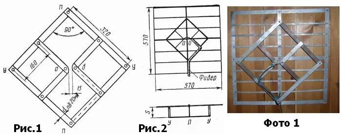
Rice. 1. The simplest homemade Z-antenna, known under the names: “Rhombus”, “Square” and “People’s Zigzag”As can be seen from the sketch (B Fig. 1), the device is a simplified version of the classic zigzag (Z-design). To increase sensitivity, it is recommended to equip it with capacitive inserts (“1” and “2”), as well as a reflector (“A” in Fig. 1). If the signal level is quite acceptable, this is not necessary.
The material you can use is aluminum, copper, and brass tubes or strips 10-15 mm wide. If you plan to install the structure outdoors, it is better to abandon aluminum, since it is susceptible to corrosion. Capacitive inserts are made of foil, tin or metal mesh. After installation, they are soldered along the circuit.
The cable is laid as shown in the figure, namely: it did not have sharp bends and did not leave the side insert.
UHF antenna with amplifier
In places where a powerful relay tower is not located in relative proximity, you can raise the signal level to an acceptable value using an amplifier. Below is a schematic diagram of a device that can be used with almost any antenna.
 Rice. 2. Antenna amplifier circuit for the UHF range
 List of elements:
- Resistors: R1 – 150 kOhm; R2 – 1 kOhm; R3 – 680 Ohm; R4 – 75 kOhm.
- Capacitors: C1 – 3.3 pF; C2 – 15 pF; C3 – 6800 pF; C4, C5, C6 – 100 pF.
- Transistors: VT1, VT2 – GT311D (can be replaced with: KT3101, KT3115 and KT3132).
Inductance: L1 – is a frameless coil with a diameter of 4 mm, wound with copper wire Ø 0.8 mm (2.5 turns must be made); L2 and L3 are high-frequency chokes 25 µH and 100 µH, respectively.
If the circuit is assembled correctly, we will get an amplifier with the following characteristics:
- bandwidth from 470 to 790 MHz;
- gain and noise factors – 30 and 3 dB, respectively;
- the value of the output and input resistance of the device corresponds to the RG6 cable – 75 Ohm;
- the device consumes about 12-14 mA.
Let's pay attention to the method of power supply; it is carried out directly through the cable.
This amplifier can work with the simplest designs made from improvised means.
Indoor antenna made from beer cans
Despite the unusual design, it is quite functional, since it is a classic dipole, especially since the dimensions of a standard can are perfectly suitable for the arms of a decimeter range vibrator. If the device is installed in a room, then in this case it is not even necessary to coordinate with the cable, provided that it is not longer than two meters.

Designations:
- A - two cans with a volume of 500 mg (if you take tin and not aluminum, you can solder the cable instead of using self-tapping screws).
- B – places where the cable shielding is attached.
- C – central vein.
- D – place of attachment of the central core
- E – cable coming from the TV.
The arms of this exotic dipole must be mounted on a holder made of any insulating material. As such, you can use improvised things, for example, a plastic clothes hanger, a mop bar or a piece of wooden beam of appropriate size. The distance between the shoulders is from 1 to 8 cm (selected empirically).
The main advantages of the design are fast production (10 - 20 minutes) and quite acceptable picture quality, provided there is sufficient signal power.
Making an antenna from copper wire
There is a design that is much simpler than the previous version, which only requires a piece of copper wire. We are talking about a narrow band loop antenna. This solution has undoubted advantages, since in addition to its main purpose, the device plays the role of a selective filter that reduces interference, which allows you to confidently receive a signal.
 Fig.4. A simple UHF loop antenna for receiving digital TV
 For this design, you need to calculate the length of the loop; to do this, you need to find out the frequency of the “digit” for your region. For example, in St. Petersburg it is broadcast on 586 and 666 MHz. The calculation formula will be as follows: L R = 300/f, where L R is the length of the loop (the result is presented in meters), and f is the average frequency range, for St. Petersburg this value will be 626 (the sum of 586 and 666 divided by 2). Now we calculate L R, 300/626 = 0.48, which means the length of the loop should be 48 centimeters.
If you take a thick RG-6 cable with braided foil, it can be used instead of copper wire to make a loop.
Now let's tell you how the structure is assembled:
- A piece of copper wire (or RG6 cable) with a length equal to L R is measured and cut.
- A loop of suitable diameter is folded, after which a cable leading to the receiver is soldered to its ends. If RG6 is used instead of copper wire, then the insulation from its ends is first removed, approximately 1-1.5 cm (the central core does not need to be cleaned, it is not involved in the process).
- The loop is installed on the stand.
- The F connector (plug) is screwed onto the cable to the receiver.
Note that despite the simplicity of the design, it is most effective for receiving “digits”, provided that the calculations are carried out correctly.
Do-it-yourself MV and UHF indoor antenna
If, in addition to UHF, there is a desire to receive MF, you can assemble a simple multiwave oven, its drawing with dimensions is presented below.

To amplify the signal, this design uses a ready-made SWA 9 unit; if you have problems purchasing it, you can use a homemade device, the diagram of which was shown above (see Fig. 2).
It is important to maintain the angle between the petals; going beyond the specified range significantly affects the quality of the “picture”.
Despite the fact that such a device is much simpler than a log-periodic design with a wave channel, it nevertheless shows good results if the signal is of sufficient power.
DIY figure eight antenna for digital TV
Let's consider another common design option for receiving “digits”. It is based on the classic scheme for the UHF range, which, because of its shape, is called “Figure Eight” or “Zigzag”.
 Rice. 6. Sketch and implementation of the digital eight
 Design dimensions:
- outer sides of the diamond (A) – 140 mm;
- internal sides (B) – 130 mm;
- distance to the reflector (C) – from 110 to 130 mm;
- width (D) – 300 mm;
- the pitch between the rods (E) is from 8 to 25 mm.
The cable connection location is at points 1 and 2. The material requirements are the same as for the “Rhombus” design, which was described at the beginning of the article.
Homemade antenna for DBT T2
Actually, all of the examples listed above are capable of receiving DBT T2, but for variety we will present a sketch of another design, popularly called “Butterfly”.

The material can be used as plates made of copper, brass, aluminum or duralumin. If the structure is planned to be installed outdoors, then the last two options are not suitable.
Bottom line: which option to choose?
Oddly enough, the simplest option is the most effective, so the “loop” is best suited for receiving a “digit” (Fig. 4). But, if you need to receive other channels in the UHF range, then it is better to stick with “Zigzag” (Fig. 6).
The antenna for the TV should be directed towards the nearest active repeater, in order to select the desired position, you should rotate the structure until the signal strength is satisfactory.
If, despite the presence of an amplifier and reflector, the quality of the “picture” leaves much to be desired, you can try installing the structure on a mast.

In this case, it is necessary to install lightning protection, but this is a topic for another article.