Repair of Genius active speakers. Repair of Genius active speakers Repair of Genius computer speakers
If any malfunction occurs with the speakers, you can take them to a service center, or you can, if you wish, disassemble them and independently determine the cause of the failure, and maybe eliminate it.
You will need
- - screwdriver.
Instructions
Recently, Genius active speakers were brought in for repair. The owner, not understanding electronics, tried to connect the speakers in the car, and as a result, after opening it, it became clear that all the amplifiers had been burned. In addition, several lines on the board were broken.
The speakers turned out to be quite powerful, since they had 70-watt heads with a load resistance of 8 ohms.
For each channel there was a separate amplifier on two microcircuits; when bridged, the microcircuits provide up to 65 watts.
If, when power is applied, the heat sink of the microcircuits begins to overheat terribly in a matter of seconds, then we can conclude that the microcircuits are not working.
The test here is simple, first you need to unsolder the microcircuits, then check for the presence of voltage on the smoothing capacitors.

We connect one of the multimeter leads to ground (the middle point of the transformer), the other to the plus or minus of one of the capacitors, then the other capacitor. The ground-minus and ground-plus voltages should be the same, in my case 17 Volts, that is, the amplifier is powered from a bipolar source of 32 Volts.
After this, we carefully look at the board from the parts side, paying special attention to the electrolytic capacitors and resistors. If you find a suspicious resistor, it is advisable to test it with a multimeter. If you find swollen capacitors, they should be replaced.
Then we check the presence of voltage on the fifth and third legs of each microcircuit; it should be in the region of 30-34 Volts. If there is no voltage, then check the board with jumpers again for breaks.
It was necessary to equip a computer workstation. In order to save money, I decided to restore and repair old “Genius” computer speakers. The speakers are strong, in a durable case and with a decent acoustic emitter, but the electronics gave rise to criticism. Using affordable and cheap electronic modules purchased from online stores, I was able to make loud speakers with clear sound with my own hands. Computer speakers turned out to be cheaper in their parameters than similar acoustics purchased in a store. Provides detailed step-by-step instruction repair with diagram, photo and video.
Do-it-yourself repair of Genius computer speakers

Computer speakers “Genius SP-16” were taken for restoration and repair. Speakers began their life in the days of 14″ computer cathode-ray monitors. The cases are made of durable plastic with sufficient internal volume. Inside the speakers there are speakers with high efficiency and good playback performance. But there are complaints about the electronics, which were partially eliminated during operation (replacing electrolytic capacitors). Unfortunately, the sound from the speakers was not High Quality, especially at high volumes, non-linear distortions were clearly visible and annoying.
The following restoration scheme was used for repairs:
- Replace the existing low-frequency amplifier with a Class D amplifier.
- Save the main controls for the operation of the speakers.
- Use an existing transformer to power the speakers.


For the repair, a ready-made 5 Volt 2 Ampere switching power supply stabilizer and a digital stereo ULF board (3 Watts per channel) were used. This type The ULF was deliberately chosen because of its low cost (~15 rubles) and unpretentiousness. Stereo amplifier purchased on Aliexpress using this link http://ali.pub/1e25ap . And an adjustable voltage stabilizer at this link http://s.click.aliexpress.com/e/i6eamub . Buy 10 amplifiers at once, believe me, they will come in handy, at this price it’s free!
To work, you will need a long Phillips screwdriver, a soldering iron with soldering accessories and pieces of tinned and insulated copper conductors. Having a solder suction will make dismantling work easier. To control soldering and settings, you will need a tester.

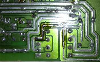
 Genius speakers - diagram
 The photo shows the diagram of the “Genius SP-16” speaker. In the diagram, crosses indicate conductors with parts. All parts to the right of the cross must be desoldered and removed. The numbers show the connection points for the ULF board and power supply.
Repair procedure for the “Genius SP-16” speaker
- Unscrew the screws securing the halves of the active column cover
- The board is removed from the open case and the power and speaker connections are unsoldered.
- The board is removed from the case and the radio components are removed from it according to the diagram.
- On the back side of the board, a power stabilizer is installed using a soldering iron on the conductor legs according to the diagram. Before installing the ULF on the board, you need to apply power to the board and check output voltage to the stabilizer +5 Volt.
- Next, a ULF board is installed on the board in the same way on the tinned conductors. The signal to the jack of the external speaker and the speakers of the speaker is supplied by insulated conductors. See photo.
- Before final assembly, we check the operation of the ULF and volume and tone controls.
- Assembling the speaker housing. See the video for sound quality.

 Disassembling the case
 Column panel removed


 Conductors are soldered off


 Details removed
 Fee installed