Do-it-yourself color music. Various schemes of color and music machines
LEDs are used as emitters. The circuit does not require configuration and starts working immediately after assembly. To change the brightness of the LEDs, you can select resistor values. Input circuits can be combined to supply a signal from a single source. Any coil L can be selected experimentally and can be completely excluded from the circuit.
In this version of the color music circuit, 220 Volt lamps are used as a load. The device is assembled using passive elements as frequency filters; KU202 thyristors are used as control triggers. Any transformer, with a ratio of 1 to 2 ... 1 to 5.
The tracking circuit is controlled using semiconductor transistors. Transformer T1 has a transformation ratio of 1 to 1. The approximate resistance of any winding is DC– not less than 200 Ohm. The supply transformer must have an output of 15-18 Volts. Load current is not less than 0.1 Ampere.

In this article we will talk about color music. Probably every beginning radio amateur, and not only others, at one time or another had the desire to assemble color music. What this is, I think, is known to everyone - to put it simply, this is a creation visual effects, changing to the beat of the music.
That part of color music that emits light can be done using powerful lamps, for example, in a concert setup; if color music is needed for home discos, it can be done using ordinary 220 volt incandescent lamps, and if color music is planned, for example, as computer modding, for everyday use, it can be done with LEDs.

Recently, with the advent of LED strips on sale, color and music consoles using such LED strips are increasingly used. In any case, to assemble Color Musical Installations (CMUs for short) a signal source is required, which can be a microphone with several amplifier stages assembled.

The signal can also be taken from the linear output of the device, sound card computer, from the output of an mp3 player, etc., in this case you will also need an amplifier, for example two stages on transistors, I used KT3102 transistors for this purpose. The preamplifier circuit is shown in the following figure:

Preamplifier - circuit
The following is a diagram of a single-channel color music with a filter, working in conjunction with a preamplifier (above). In this circuit, the LED flashes along with the bass (low frequencies). To match the signal level, a variable resistor R6 is provided in the color music circuit.

There are also simpler color music circuits that any beginner can assemble, using 1 transistor, and also not requiring a preamplifier; one of these circuits is shown in the picture below:

Color music on a transistor
The pinout diagram for the Jack 3.5 plug is shown in the following figure:

If for some reason it is not possible to assemble a pre-amplifier using transistors, you can replace it with a transformer turned on as a step-up. Such a transformer must produce voltage on the windings of 220/5 Volts. The transformer winding with a smaller number of turns is connected to a sound source, for example, a radio tape recorder, parallel to the speaker, and the amplifier must produce a power of at least 3-5 watts. A winding with a large number of turns is connected to the color music input.
![]()
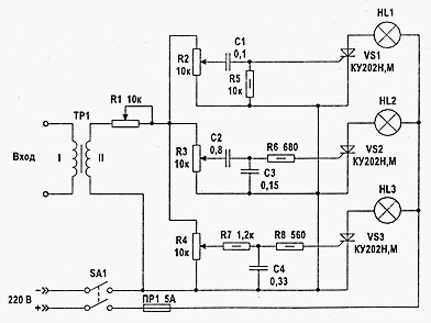
Of course, color music is not only single-channel, it can be 3, 5 or more multi-channel, when each LED or incandescent lamp blinks while reproducing the frequencies of its range. In this case, the frequency range is set by using filters. In the following circuit, a three-channel color music system (which I recently assembled myself), there are capacitors as filters:

If we wanted to use not individual LEDs in the last circuit, but an LED strip, then the current-limiting resistors R1, R2, R3 should be removed from the circuit. If the strip or LED is used RGB, it must be made with a common anode. If you plan to connect LED strips long, then to control the tape you should use powerful transistors installed on radiators.

Since LED strips are designed for a power supply of 12 Volts, accordingly, we should raise the power supply in the circuit to 12 Volts, and the power supply should be stabilized.
Thyristors in color music
Until now, the article has only talked about color and music devices using LEDs. If there is a need to assemble a digital control unit using incandescent lamps, then thyristors will need to be used to control the brightness of the lamps. What is a thyristor anyway? This is a three-electrode semiconductor device, which accordingly has Anode, Cathode And Control electrode.

KU202 Thyristor
The figure above shows the Soviet thyristor KU202. Thyristors, if you plan to use them with a powerful load, also need to be mounted on a heat sink (radiator). As we see in the figure, the thyristor has a thread with a nut and is attached similarly to powerful diodes. Modern imported ones are simply equipped with a flange with a hole.

One of these thyristor circuits is shown above. This is a three-channel color music circuit with a step-up transformer at the input. When selecting analogue thyristors, you should look at the maximum permissible voltage of the thyristors, in our case for the KU202N it is 400 volts.

The figure shows a similar color music circuit to the one shown above, the main difference in the lower circuit is that there is no diode bridge. Also, LED color music can be built into system unit. I assembled such a three-channel color music with a preamplifier in a casing from a cider. In this case, the signal was taken from the computer sound card using a signal divider, the outputs of which were connected active acoustics and color music. It is possible to adjust the signal level, both overall and separately by channel. The preamplifier and color music were powered from a 12 Volt Molex connector (yellow and black wires). The preamplifier and three-channel color music circuits for which they were assembled are shown above. There are other LED color music schemes, for example this one, also three-channel:

Color music on 3 LEDs - diagram
In this circuit, unlike the one I assembled, inductance is used in the mid-frequency channel. For those who want to first assemble something simpler, here is the following diagram for 2 channels:

If you collect color music using lamps, you will have to use light filters, which in turn can be either homemade or purchased. The figure below shows the filters that are commercially available:

Some fans of color and musical effects assemble devices based on microcontrollers. Below is a diagram of four-channel color music on the AVR tiny 15 MK:

The Tiny 15 microcontroller in this circuit can be replaced with tiny 13V, tiny 25V. And at the end of the review, I would like to say on my own that color music using lamps is inferior in terms of entertainment to color music using LEDs, since lamps are more inertial than LEDs. And for self-repetition, I can recommend this one:
This simplest light music has only one element. Yes, absolutely alone and nothing but: no resistors, no transistors... It is quite possible to assemble such a light and music installation in 30 minutes. All you need is one solid state relay.
Solid-state relays appeared on the market relatively recently and have already confidently conquered the radio electronics market. It’s understandable, I’ll give you the main advantages.
- - Performance.
- - Galvanic voltage isolation.
- - Quiet compared to a conventional relay.
- - Zero crossing detector.
A solid-state relay, in essence, apart from the name, has nothing in common with a mechanical relay, which everyone usually imagines when hearing this name for the first time. This is a regular triac switch, with control and decoupling circuits.
This miracle is quite inexpensive and can be easily bought on our favorite Aliexpress.com
There are many different versions of relays on the radio market: small and large, powerful and low-power. I took this:
Firstly, it has screw terminals for connection. Secondly, it can switch a load with a voltage of 24-380 V and a current of up to 60 A. Of course, I took it overkill for other purposes. To control a garland, it is enough to take from 2 A. Thirdly, the control voltage is from 3 to 32 volts, pulsed. Just what we need, since we will control the relay directly with the sound supplied from the output of the low-frequency amplifier.
Light and music circuit

A solid-state relay is connected to the open circuit of a lamp or garland. And the sound from the speaker is supplied to the input of the solid-state relay. The scheme couldn't be simpler. The main thing is not to confuse the conclusions. Now, as soon as the music starts playing in the speaker, the garland will immediately start blinking in time with the music.
We take the output from the amplifier from any channel, left or right. You can connect between the outputs so that the garland flashes with a stereo effect. If there is a subwoofer output, you can connect it to it. Or you can take two garlands and two relays and connect to different channels. There are a lot of options, choose any one you like.

I added a park of toggle switches to the circuit for switching. The first toggle switch in the diagram is so that you can simply turn on the garland in normal mode. And the second is to turn off the influence of music on her.
Thanks to galvanic isolation, high mains voltage is reliably isolated and will not pass through the speaker and amplifier.
I took a plastic container and placed sockets there to connect the load. I made holes for the toggle switches and connected the entire system.
Structurally, any color and music (light and music) installation consists of three elements. Control unit, power amplification unit and optical output device.
As an output optical device, you can use garlands, you can design it in the form of a screen (classic version) or use electric directional lamps - spotlights, headlights.
That is, any means are suitable that allow you to create a certain set of colorful lighting effects.
The power amplification unit is an amplifier(s) using transistors with thyristor regulators at the output. The voltage and power of the light sources of the output optical device depend on the parameters of the elements used in it.
The control unit controls the intensity of light and the alternation of colors. In complex special installations designed to decorate the stage during various types of shows - circus, theatrical and variety performances, this block is controlled manually.
Accordingly, the participation of at least one, and at most, a group of lighting operators is required.
If the control unit is controlled directly by music and works according to any given program, then the color and music installation is considered automatic.
It is precisely this kind of “color music” that novice designers - radio amateurs - have usually assembled with their own hands over the past 50 years.
The simplest (and most popular) “color music” circuit using KU202N thyristors.

This is the simplest and perhaps the most popular scheme for a color and music console based on thyristors.
Thirty years ago I first saw a full-fledged, working “light music” up close. It was assembled by my classmate, with the help of my older brother. It was exactly this scheme. Its undoubted advantage is its simplicity, with a fairly obvious separation of the operating modes of all three channels. Lamps do not flash simultaneously, red channel low frequencies blinks steadily in rhythm with the drums, the middle green one responds in the range of the human voice, the high frequency blue one reacts to everything else subtle - ringing and squeaking.
There is only one drawback - a 1-2 watt pre-amplifier is required. My friend had to turn his “Electronics” almost “fully” in order to achieve a sufficiently stable device operation. A step-down transformer from a radio point was used as an input transformer. Instead, you can use any small-sized step-down network trans. For example, from 220 to 12 volts. You just need to connect it the other way around - with a low-voltage winding to the amplifier input. Any resistors, with a power of 0.5 watts. Capacitors are also any; instead of KU202N thyristors, you can take KU202M.
"Color music" circuit using KU202N thyristors, with active frequency filters and a current amplifier.

The circuit is designed to operate from a linear audio output (the brightness of the lamps does not depend on the volume level).
Let's take a closer look at how it works.
The audio signal is supplied from the linear output to the primary winding of the isolation transformer. From the secondary winding of the transformer, the signal is supplied to active filters, through resistors R1, R2, R3 regulating its level.
Separate adjustment is necessary to configure the high-quality operation of the device by equalizing the brightness level of each of the three channels.

Using filters, signals are divided by frequency into three channels. The first channel carries the lowest frequency component of the signal - the filter cuts off all frequencies above 800 Hz. The filter is adjusted using trimming resistor R9. The values of capacitors C2 and C4 in the diagram are indicated as 1 µF, but as practice has shown, their capacity should be increased to at least 5 µF.

The filter of the second channel is set to medium frequency - from approximately 500 to 2000 Hz. The filter is adjusted using trimming resistor R15. The values of capacitors C5 and C7 in the diagram are indicated as 0.015 μF, but their capacity should be increased to 0.33 - 0.47 μF.

The third, high-frequency channel carries everything above 1500 (up to 5000) Hz. The filter is adjusted using trimming resistor R22. The values of capacitors C8 and C10 in the circuit are indicated as 1000 pF, but their capacitance should be increased to 0.01 μF.

Next, the signals of each channel are individually detected (germanium transistors of the D9 series are used), amplified and fed to the final stage.
The final stage is performed on powerful transistors, or on thyristors. In this case, these are KU202N thyristors.

Next, there is an optical device, the design and external design of which depends on the imagination of the designer, and the filling (lamps, LEDs) depends on the operating voltage and maximum power of the output stage.
In our case, these are 220V, 60W incandescent lamps (if you install thyristors on radiators - up to 10 pcs per channel).
The order of assembling the circuit.
About the details of the console.
KT315 transistors can be replaced with other silicon ones npn transistors with a static gain of at least 50. Fixed resistors - MLT-0.5, variable and tuning - SP-1, SPO-0.5. Capacitors - any type.
Transformer T1 with a ratio of 1:1, so you can use any one with a suitable number of turns. If you make it yourself, you can use a Sh10x10 magnetic circuit, and wind the windings with PEV-1 wire 0.1-0.15, 150-300 turns each.
The diode bridge for powering thyristors (220V) is selected based on the expected load power, minimum 2A. If the number of lamps per channel is increased, the current consumption will increase accordingly.
To power transistors (12V), you can use any stabilized power supply designed for an operating current of at least 250 mA (or better, more).
First, each color music channel is assembled separately on a breadboard.
Moreover, the assembly begins with the output stage. Having assembled the output stage, check its functionality by applying a sufficient level signal to its input.
If this cascade works normally, an active filter is assembled. Next, they check again the functionality of what happened.
As a result, after testing we have a really working channel.
In a similar way, it is necessary to collect and rebuild all three channels. Such tediousness guarantees the unconditional functionality of the device after “fine” assembly on the circuit board, if the work is carried out without errors and using “tested” parts.
Possible printed circuit mounting option (for textolite with one-sided foil coating). If you use a larger capacitor in the lowest frequency channel, the distances between the holes and conductors will have to be changed. The use of PCB with double-sided foil may be a more technologically advanced option - it will help get rid of hanging jumper wires.

Use of any materials from this page is permitted provided there is a link to the site


