Self-repair of a phone charger. We disassemble the charger from a Siemens mobile phone
As a rule, repairing such an inexpensive device is not economically profitable.
Especially in non-poor countries. Average price 5 dollars.
But it happens that there is no extra money, but there is time and spare parts.
There is no store nearby. Circumstances do not allow. Then it's not about price.
In my case, everything was simple - one of my two chargers broke Nokia AC-3E, friends brought a bag of broken chargers. Among them were a dozen branded Nokia chargers. It was a sin not to take it.
The search for the circuit did not lead to anything, so I took a similar one and converted it to the AC-3E. Many chargers for mobile phones are made using a similar scheme. As a rule, the difference is insignificant. Sometimes the values are changed, a little more or a little less elements, sometimes a charge indication is added. But basically the same thing.
That's why this description and the diagram will be useful for repairing not only the AC-3E.
The repair instructions are simple and written for non-specialists.
The scheme is clickable and of good quality. 
THEORY.
The device is a blocking oscillator operating in a self-oscillating mode. It is powered by a half-wave rectifier (D1, C1) with a voltage of approximately +300 V. Resistor R1, R2 limits the starting current of the device and acts as a fuse. The blocking oscillator is based on a transistor MJE13005 and a pulse transformer. A necessary element of the blocking generator is a positive circuit feedback formed by winding 2 of the transformer, elements R5, R4 C2.
The 5v6 zener diode limits the voltage at the base of the MJE13005 transistor to within five volts.
Damper circuit D3, C4, R6 limits voltage surges on winding 1 of the transformer. At the moment the transistor is turned off, these surges can exceed the supply voltage several times, so the minimum permissible voltage of capacitor C4 and diode D3 must be at least 1 kV.
PRACTICE.
1. Disassembly. Self-tapping screws holding the charger cover in this device They look like a triangular star. As a rule, there is no special screwdriver at hand, so you have to get out as best you can. I unscrewed it with a screwdriver, which, over the course of its use, had become sharpened into all sorts of crosses.


Sometimes chargers are assembled without bolts. In this case, the body halves are glued together. This indicates the low cost and quality of the device. Disassembling such a memory is a little more difficult. You need to split the body with a non-sharp screwdriver, gently pressing on the joint of the halves.
2. External inspection of the board. More than 50% of defects can be detected through external inspection. Burnt resistors and a darkened board will show you the location of the defect. A burst case or cracks on the board will indicate that the device was dropped. Chargers are used in extreme conditions, so falls from anywhere are a common cause of failure.
In five out of ten memory systems that I had the opportunity to do, they were trivial contacts bent through which 220 volts are supplied to the board.

To fix it, just slightly bend the contacts towards the board.
You can check whether the contacts are at fault or not by soldering the power cord to the board and measuring the voltage at the output - the red and black wires.


3.
Broken cord at the output of the charger. It usually breaks at the plug itself or at the base of the charger. Especially for those who like to talk while charging the phone.
Called the device. Insert the lead of a thin part into the center of the connector and measure the resistance of the wires.
4.
Transistor + resistors. If there is no visible damage, first of all you need to unsolder the transistor and ring it. It must be borne in mind that the transistor
MJE13005 the base is on the right, but it also happens the other way around. The transistor may be of a different type, in a different housing. Let's say MJE13001 looks like a Soviet KT209 with the base on the left.

Instead I installed MJE13003. You can install a transistor from any burnt-out lamp - a housekeeper. In them, as a rule, the filament of the bulb itself burns out, but the two high-voltage transistors remain intact.
5. Consequences of overvoltage. In the simplest case, they are expressed in a short-circuited diode D1 and a broken resistor R1. In more complex cases, the MJE13005 transistor burns out and inflates capacitor C1. All this simply changes to the same or similar details.
In the last two cases, in addition to replacing the burnt conductors, you will need to check the resistors around the transistor. With the diagram this will be easy to do.
Very often, equipment breakdowns are so basic and easily fixable that sometimes you don’t even want to take on repairs, it’s not of interest, but you have to. Recently, an acquaintance of mine turned to me for help, who had previously lived poorly, and recently, due to the crisis, also lost his job.
Shows universal type charger Frog for lithium batteries from phones, with broken fastenings of the pressing part, and asks if anything can be done. He says they sat on her. The first thought was to suggest throwing it away and buying a new one, but looking at his face, saddened by the breakdown, I changed my mind and decided to help.

There were two new crocodiles available in insulation, only the tip protruded, and it was decided to solder to the wires going to the antennae and connect to the battery with crocodiles. I plugged the charger into the socket to make sure that it worked at all, and my efforts would not be in vain, and began to disassemble it.

First, 2 screws were unscrewed, securing the antennae to the part that presses the battery; the antennae were intact. Often during work these antennae break off and it becomes impossible to use, so I kept the antennae as a reserve. If anyone doesn’t know how to use such a charger, I’ll explain: we take a lithium ion battery, from cell phone, camera and other similar equipment. We combine the antennae of the charger with its plus and minus contacts, they are labeled on the battery, and press the battery against the charger body using the spring of the pressing part. The LED on the charger should light up, indicating that there is contact between the antennae and the battery contacts. For those who may need to send a similar charger, with a more serious breakdown, I will give one of the circuit diagram options:
Charger circuit

Let's return to our repair, unscrewing two screws and disassembling the frog body. It remained to determine which of these wires going to the antennae is positive and which is negative. Such a check is rather arbitrary, because such chargers have, or automatic detection polarity, and then there are no buttons, or there is a polarity reversal button.

But still, I wanted to assemble it so that the red probe was a plus and the black probe was a minus. Then I removed the board and found a common wire connected to one of the wires; it was connected to the polygon on the board. It was decided to count it as a minus. Then it was a matter of technology; we needed beautiful wires to connect with the wires coming from the antennae. I just had the same wiring from the computer speaker. The speaker itself and the connector were cut off; I decided to take the length of the wires sufficient for easy connection to the battery contacts.

Recently, I have acquired the habit of paying attention to the aesthetics of connections in a device, no matter whether I make it for myself or for people, for money or for purely symbolic gratitude. Therefore, I bought myself a supply of heat shrinks, of different diameters, for all occasions, and decided to abandon the snot on connections in the form of electrical tape. Which, by the way, not only looks ugly, but also tends to slide off the wire connection over time and expose it. I don’t think I need to explain to anyone what this entails.

So here, too, before soldering the wires, I put two pieces of heat shrink on the wires, and after soldering, he heated them over a fire with lighters. The result is beautiful, reliable insulation. By the way, in the West, judging by the insulation of LEDs and buttons, computer cases, they have long abandoned the use of electrical tape and package everything that remains for long-term use only in heat shrink. Before soldering the wires, out of habit, I tied the wires in a knot, so that it would be impossible to pull out the wires by using force. A unit whose size is larger than the hole into which the wire is inserted in the charger body will not allow you to do this.

All that remains is to assemble the charger in the case and test it by plugging it into the network and connecting it with crocodile clips to the battery contacts. Everything worked as it should, the LED began to blink, indicating that the battery was charging. And as it turned out, I was not mistaken with the polarity and color of the crocodiles when soldering the wires. Happy repairs everyone! The author of the article is AKV.
I wonder what the Siemens charger (power supply) consists of and whether it is possible to repair it yourself if it breaks.
First, the block needs to be disassembled. Judging by the seams on the body, this unit is not intended for disassembly, therefore it is a disposable item and you don’t have to place much hope in the event of a breakdown.

I literally had to tear apart the body charger, it consists of two tightly glued parts.

Inside is a primitive circuit board and several parts. The interesting thing is that the board is not soldered to the 220V plug, but is attached to it using a pair of contacts. In rare cases, these contacts may oxidize and lose contact, leaving you thinking the unit is broken. But I was pleasantly pleased with the thickness of the wires going to the connector for the mobile phone; you don’t often see a normal wire in disposable devices; usually it is so thin that it’s scary to even touch it).
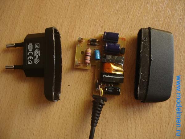
There were several parts on the back of the board; the circuit turned out to be not so simple, but still not so complicated that you couldn’t fix it yourself.

Below in the photo are the contacts of the inside of the case.

There is no step-down transformer in the charger circuit; its role is played by an ordinary resistor. Next, as usual, a couple of rectifying diodes, a pair of capacitors for rectifying the current, then comes a choke and finally a zener diode with a capacitor completes the chain and outputs the reduced voltage to a wire with a connector to the mobile phone.

The connector has only two contacts.

Causes of mobile phone charger malfunctions
Most common cause failure of the memory device is a careless attitude towards it during operation.
Phone charger repair
Possible causes of breakdowns of the mobile phone charging unit
1. Broken wire at the plug and at the base of the charging unit. You can break the wires when charging is on during calls.
You need to pull the plug out of the phone socket not by the wire, but by the plug body.
2. Failure of elements of the electronic board of the charger. Very often the charger is left plugged in and not removed from the outlet. In this case, the entire electronic board of the charger is constantly under voltage, which reduces the service life of the board's radio elements.
Incorrect order of turning on and off the charger also leads to premature wear of the unit elements.
If you disconnect the phone from the charger under voltage, sudden voltage surges occur that exceed the maximum permissible operating voltages of the elements. This is due to transient processes that occur in the memory when the load is removed (the phone is turned off) under voltage. At correct operation The phone charger is connected and disconnected with the charging switched off.
Do-it-yourself method for repairing a phone charger
You don't need to be a big specialist to find and repair a broken wire from the charging unit to the plug. Damage to the wire can be determined when the phone is connected. Having connected the phone to charging, bend the wire at the plug u of the base of the unit, while simultaneously monitoring the continuity of the battery charging process.
These are the places where wire breaks most often occur. If a break is found at the very base of the plug, then cut the wire at a distance of 5-7 mm from the plug. This is necessary in order to be able to solder an entire part of the wire. The soldered wires are insulated separately with a thin heat-shrinkable tube.
When the places where the wires are soldered are insulated, a thicker heat-shrink tube is placed on the plug to make the soldering area rigid. Sometimes a wire break occurs at the very base of the plug, then the plug is completely freed from the plastic seal and the wires are soldered directly to the plug.
Do not reverse the polarity of the plug wires. The break point is also found with a multimeter in audio testing mode or visually. The found location of the wire break is cut off with a small margin on both sides. Clean the wire from the top insulation. Then it is cut, stripped of insulation, twisted and soldered, having previously placed a thin heat-shrink tube on each wire, and a thicker tube on the common wire.
After soldering, put thin tubes on the wires and deposit them, heating them with a soldering iron. At the end, a thicker tube is put in place of the deposited thin tubes so that the thick tube overlaps them in length. When soldering wires, observe the polarity according to their color. A new cable with a plug for your phone brand can be purchased at specialized stores. Then repairing the phone comes down to simply replacing the faulty wire.

Type of faulty capacitors
Another common malfunction of a phone charger is a failure of contact between the pins of the power plug. The spring contacts of the power plug often move away from the contact pads on the printed circuit board. To eliminate such a malfunction, it is enough to bend these contacts located inside the block.
Open the block cover. It is good if there are screws securing the charger cover, and if they are soldered. In this case, you need to use a hacksaw blade with fine teeth to cut a slot around the entire perimeter of the lid. Having eliminated the malfunction, close the lid and secure it with 1 cm wide tape.
More complex, but quite accessible to an electrician, are device breakdowns associated with repairing elements of the phone charger board. First of all, they open the memory and take out the board. The repair begins with a visual inspection of the elements of the printed circuit board and the condition of its tracks.

Scheme of a pulse charger for a phone
When inspecting the elements, pay attention to swelling of the upper part of the capacitors, darkening and damage to the integrity of the resistors. Darkening of the resistors and tracks underneath indicates that the operating temperature has been exceeded. In this case, the resistor itself is checked for resistance and the diodes and transistors are tested.
The transistor pinout and memory circuit for your phone brand can be found on the Internet. If the malfunction cannot be visually detected, turn on the device and measure the input mains voltage. If the mains voltage is present and a faint sound of the pulse transformer is heard, then measure output voltage block.

Today, many people use portable devices. The latter work autonomously and require periodic charging. For this purpose, special power supplies are used to connect the device to the mains. The charger must charge the phone, player, netbook in a certain time. If it does not cope with its functions, we are talking about a possible breakdown.
The charger can be replaced with a new one. This method is simple and accessible. But experts recommend repairing the original device. It is much more reliable than analogues and replicas on the market today. You will learn how to repair the charger yourself from the instructions below.
Device diagnostics
The basis of competent repair has always been and remains high-quality diagnostics. It is important to determine the cause of the charging failure. There may be several of these. The most common: plug malfunction, board coming out of position, wire malfunction. Most often, chargers are thrown away for the latter reason. But a broken wire is not a reason to spend money on a new device. This problem can be easily fixed with your own hands.
Charging repair: stages
If the charger has a broken wire near the power supply, you must do the following:
- Disassemble the charger (unscrew the mounting bolts, remove the case).
- Cut off the broken wire and secure it with a knot in the charging case.
- Clean the ends of the wire.
- Unsolder the broken piece of wire remaining on the board (carefully so as not to overheat the sensitive element).
- Solder the stripped wire in place of the old one.
- Test the device.
If the phone is charging, the power supply can be assembled. If not, most likely the wire is broken somewhere else. In this case, the easiest way is to replace it with a new one by attaching it to the block and plug.
If the plug itself is faulty, it can be easily replaced with a new one. It is necessary to select an element of the appropriate format. The plug can be purchased from parts stores. mobile devices or use a part from another device of a similar type and purpose.
More serious damage to the charger, as a rule, cannot be repaired. If the board burns out, theoretically it can be replaced with a new one. But there may be problems finding spare parts. In this case, it is recommended to purchase a new charger.


