Review of the ASUS Crosshair V Formula-Z motherboard. ASUS Crosshair V Formula-Z: from a cannon to sparrows Asus crosshair v formula memory installation
Not only overlockers and gaming enthusiasts want to have a reliable and multifunctional motherboard at hand to create a powerful home computer. Many ordinary users whose leisure time is inextricably linked with multimedia, or whose professional interest involves working with 3D modeling, photo editing and video processing, definitely need to own a decent motherboard that can combine many of the necessary computer components into a full-fledged working platform.
This article focuses on a real monster of the computer market - the Asus Formula Z Crosshair V motherboard. The characteristics, reviews and photos presented to the reader will allow the potential buyer to learn a lot of useful and interesting things about the product.
True Republican
Yes, it’s not every day that you can find motherboards for the AM3+ platform on store shelves, costing about 15-18 thousand rubles. In fact, this is the price of a budget laptop, not a basic computer component. However, it is the Asus ROG Crosshair V Formula Z board, the review of which is offered to the reader, that is the most expensive device on the world market for the AM3+ socket.
The fault is not in the functionality that the device is equipped with, but in the build quality. After all, this motherboard belongs to the ROG (Republic of Gamers) series, and accordingly, it is manufactured with higher requirements for computer components on the global market. In simple terms, this motherboard is a masterpiece, a benchmark and is not only capable of working in extreme conditions, but also has high fault tolerance. Asus ROG is a guarantor!
First meeting
Many owners often complain in their reviews about manufacturers who pay too much attention to the beautiful packaging in which computer components are transported. However, it is a well-made box that allows the buyer to purchase a fully working device that is not damaged during transportation.
The Asus Crosshair V Formula Z motherboard comes in a package made of very thick cardboard, which from a distance looks more like a sarcophagus. The box may be painted in bright colors, but its panels are quite informative and allow the buyer to get acquainted with the characteristics of the device.
As for the configuration, the user has nothing to worry about here either; the manufacturer has done everything possible to please the user. In addition to the huge instruction manual and software discs, the owner will find a lot of useful things in the box:
- six SATA cables (3 of them have an L-shaped connector);
- one CrossFire bridge, 1 SLI bridge and a 3-Way SLI interface for connecting 3 video cards;
- USB-AA cable for connecting the ROG panel;
- many stickers for cables inside the system unit;
- branded stickers with the ROG logo and a “Do not disturb the player” sign.
The right approach
The appearance of the Asus Crosshair V Formula Z motherboard inspires respect. It is immediately clear that the manufacturer took the task seriously. It’s better to start with the fact that the processor socket is reinforced with a metal plate. Moreover, the socket is clamped on both sides of the board. This mechanism is guaranteed to protect the processor socket from damage when installing a huge cooler (theoretically, the mount can withstand a load of 2 kilograms).

As for the placement of components, here too the manufacturer managed to surprise the buyer. All elements, including slots, cooling system and even capacitors, are placed conveniently and beautifully. As users note in their reviews, very pedantic people worked on creating the board, who managed to restore order and create a truly convenient and elegant product.
Golf course
The Asus ROG Crosshair V Formula Z base board stands out from the competition in more ways than just its looks and functionality. Many potential buyers managed to pay attention to the large area around the processor socket, which is completely devoid of microcircuits and capacitors. Many users immediately ask the question: “What kind of cooling system should it be to take up all the free space near the processor?”

Yes, the gaming device initially assumes that the owner will have a powerful processor at hand, which will also be overclocked. On the other hand, no matter what the heatsink is, it simply will not transfer heat to the memory modules and northbridge capacitors, as often happens when using conventional motherboards.
There is no such thing as too much memory
Four DDR3 slots located near the processor socket will certainly please the user who plans to further improve system performance by increasing the memory. However, there is one problem that it is better for a potential buyer to know about right away. The fact is that the Asus Crosshair V Formula Z AM3 product is built on the AMD 990FX chip, which at the hardware level is limited in working with RAM.
The maximum installed capacity that the motherboard can handle is only 32 gigabytes. Yes, now it seems that the owner will not need that much RAM, but no one knows what will happen in 2 years. For example, competitor Intel has already begun to worry about a future problem, and its expensive chips support a total capacity of up to 64 gigabytes.
Correct voltage
Naturally, many potential buyers are also interested in the electrical capabilities of the Asus Crosshair V Formula Z motherboard. It is quite difficult to find a review of power elements in the media, so this gap needs to be filled. All ROG products use the proprietary Extreme Engine Digi+ II power subsystem. Its peculiarity is that the manufacturer provides each controller with its own phase. Yes, it's expensive, but very effective.

This board uses a 10-phase circuit. The manufacturer has included a digital controller on the board that is capable of manually controlling all phases. You don’t even need to start talking about high-quality chips and solid-state containers, but it’s better to go straight to the cooling system. All batteries have their own passive radiators, which perfectly dissipate heat.
Expansion slots
Four PCIex16 slots look quite impressive on the Asus Crosshair V Formula Z motherboard. The owners' reviews can be understood regarding the maximum efficiency of the gaming platform, but the manufacturer forgot to indicate in the advertising brochures that the slots are not full-fledged. The first PCIex16 slot operates at the stated speed, but the second and third share one 16-speed lane in half. It’s better not to mention the fourth slot; it works in x4 mode.
As for the placement of the slots themselves, opinions are divided here. Some users claim that the location of the PCIex16 connectors is convenient and allows you to easily install at least three powerful gaming adapters that will not interfere with each other’s cooling systems. But there are also dissatisfied owners who consider the 4th slot superfluous, since it is blocked by the heatsink of the 3rd video card.
File subsystem
The six in the kit already hint to the future owner that he can connect up to 6 hard drives to the Asus Crosshair V Formula Z AMD 990FXSB950 motherboard. In fact, the system can handle ten hard drives. The board itself contains not 6, but 8, two of which are simply based on a different chip. The board also has two eSATA ports, which can also operate at speeds of up to 6 gigabits per second.

Don't forget about the PCIex1 interface. Recently, many game lovers have come to the conclusion that the weak point in the system is still the hard drive. Therefore, many buyers prefer SSD drives that operate not only via the SATA interface, but also via the PCIex1 bus.
Generous producer
Many users have already noticed that the AMD 990FX chipset does not support the USB 3.0 controller. However, it is too early to get upset. The fact is that the Asus Crosshair V Formula Z gaming motherboard has an additional ASmedia chip installed, which provides support for popular components.
In general, there will be no problems with plug-in interfaces, since the manufacturer has provided its product with everything necessary. The only thing I can complain about is the integrated video output that is missing on the board. On the one hand, gaming boards are not equipped with budget components. On the other hand, no one knows how a motherboard with overclocked graphics accelerators will behave and whether it will be able to display an image on the display in the event of any failure.
Mission control center
Yes, the UEFI shell built into the BIOS from the manufacturer Asus knows how to impress. This is an entertaining control panel that allows you to programmatically control the operation of the entire computer hardware. The owner of the Asus Formula Z Crosshair V motherboard will have to fully study the instruction manual to understand how to properly configure the gaming platform.
As practice shows, the user has the opportunity to set not only the voltage and frequency on the system bus, but also locally change the characteristics of all slots that are installed on the board. This solution is more convenient if you need to overclock one component, rather than all at once.

Naturally, the control center not only monitors effective operation, but also a “sandbox” that allows testing in real time without restarting the system and loading Windows. Users may also like the intelligent overclocking system, which operates in automatic mode, but not all enthusiasts enjoy having their computer do the work for them.
Platform performance
Many potential buyers have always been interested in how gaming boards are tested. This is not a processor and a graphics accelerator, which can demonstrate the number of frames per second in a resource-intensive game. The Asus Crosshair V Formula Z motherboard, the characteristics of which cannot be seen visually, is tested for stability. After all, it is this factor that allows all components of the system to work without failures.
It is worth noting that this particular platform is used by many enthusiasts when measuring the performance of processors and video cards. During testing, not a single user has yet managed to burn out the system due to overheating, which means that the power management and cooling systems are up to the task.
As for the overclocking potential, there are no restrictions here either. The motherboard controller does not care which adapter or processor is installed (unless the chip multiplier can be locked at the hardware level). Everything is accelerated via the bus and power supply.
Feedback
Naturally, the proprietary panel for overclocking the Asus Formula Z Crosshair V motherboard was liked by all owners. At least, all positive user reviews begin with the UEFI shell and overclocking convenience. Game lovers were pleased with the equipment included in the device. It is quite strange that almost all owners share in the media their impressions of branded stickers and the “Do Not Disturb” sign and do not mention at all about other useful accessories in the box.

The stable operation of DDR3 RAM at a speed of 2400 MHz did not go unnoticed by overlockers. Not every product on the market is able to demonstrate similar frequency. There are no complaints about the heating of the entire platform. This is understandable; the 10-phase power stabilization system clearly fulfills its functions.
Finally
After getting acquainted with the characteristics of the Asus Formula Z Crosshair V motherboard and finding out what many owners think about it, we can draw an obvious conclusion. If you have the financial opportunity, then you should give preference to this particular product, because there is simply nothing else more productive on the computer market. Yes, there are some shortcomings regarding the limited amount of RAM, but this is incomparable to the potential of a gaming motherboard directly during operation.
elite addition to the Republic of Gamers series on the AMD 990FX chipset (Socket AM3+)
There is still some time left before the release of processors based on the Bulldozer core, but boards for Socket AM3+ are already available in a full range. And this, it should be noted, is quite good, since it allows us to exclude any accidents and roughness on the part of the platform at the time of processor release. And prices for everything new, especially on the Russian market, tend to be inflated. And then, lo and behold, by the time the processors are released, motherboards will be sold on every corner (which means they will cost adequately), and the BIOS will be cleaned up. However, the board considered in this review is unlikely to cost much less: belonging to the “luxury” segment obliges. And technically, the board is very interesting, so for a computer that is being assembled seriously and for a long time, it may well be chosen not only for reasons of prestige.
Features of the board
This time the developers did not confuse users with 5 PCI Express x16 slots, but left only four. However, the board offers the best possible means for organizing configurations with multiple video cards today. In addition to the Quad CrossFireX configuration supported by the chipset on video cards with Radeon chips, it is possible to build 3-Way SLI on GeForce. But unlike the previous version of the board, which used an additional Lucid Hydra chip, in this case, support for configurations with NVIDIA cards is provided by the 990FX chipset itself.
Actually, the main difference between the 990FX in system functionality, from the user's point of view, is that NVIDIA, shortly before the release of this chipset, opened up the possibility of licensing SLI for the AMD platform. And although NVIDIA is to a certain extent a competitor to AMD, it had no other option, since this company no longer produces its own chipsets.
The formula for distributing lines is as follows: when installing two video cards in the first and second slots, both cards receive 16 PCI Express 2.0 lines at their disposal; when installing three cards, the lines are distributed as “x16+x16+x8”. Finally, the 4th port is permanently connected to 4 PCI-E lanes.

Along the edge of the board there are buttons for turning on, restarting the computer and selecting an “overclocking” profile, which can be pre-configured in the BIOS. The Go button, located in the area of the memory slots, has also become standard, the purpose of which is to allow you to boot with increased timings and a lower memory frequency in the event that the computer does not start after installing a non-standard set of memory.

The vertical row of contacts that you see in the same photo on the right allows the overclocker user to use a multimeter to monitor the voltages of the main components: processor, memory, chipset bridges, HT bus, etc. This is hardly useful when working with standard parameters, but It will be in demand for extreme overclocking and when participating in overclocking competitions.
The board supports most proprietary technologies familiar to us from previous models in this line, including GameFirst (the ability to set guaranteed local network bandwidth for selected applications) and ROG Connect (the ability to manage overclocking settings and monitor current settings from a laptop connected via USB to a special port on the board)
The board is full of additional controllers, but unlike the previous model, it fits into the dimensions of a standard ATX format (305x245 mm), so it can be installed in any standard case.

The cooling system is passive, but the radiator occupies a fairly large area, and it has to cool not three, as in the previous case, but two chips. Therefore, if there is good ventilation in the case, it should cope with moderate overclocking. Well, extreme sports enthusiasts will still use additional cooling means.

The processor voltage regulator is significantly different from the previous board model. This is not surprising, since the main differences between Socket AM3+ and simple AM3 are precisely the improved power supply circuits. The processors themselves will contain circuits for precise “digital” control of power parameters.
We also see the possibility of using a 4-pin processor power connector (ATX12V) in addition to the standard 8-pin (EPS12V). It only makes sense to do this during overclocking. When using processors with a low TDP, the board starts and works correctly when just a 4-pin connector is connected to the main connector (you don’t even have to remove the plug from the connector).
The number of phases remains the same: the stabilizer is 10-channel, 2 high-performance field-effect transistors with Low R DS(on) are installed on each channel. There are 11 capacitors installed at 820 uF, 5 at 560 uF and 4 at 270 uF - not as many as on the previous version of the board. But it’s quite enough, since the capacitors are elite, made in Japan, with a stated service life of up to 500,000 hours at a temperature of 65 °C. It is possible to install any modern processors, including discontinued models with a TDP of 140 W.

This time the delivery package does not contain any significant additions such as a sound card or Wi-Fi adapter, which we periodically came across with boards of this series. There are 6 SATA 3.0 cables with metal latches, a cable for implementing the ROG Connect function, a set of Q-Connectors for combining wires from the front panel for easy connection to the board, and a proprietary plug for the rear panel. There are also stickers for SATA cables and cable ties.
Functionality
The board is based on the AMD 990FX chipset, which from the point of view of peripheral functionality is a complete analogue of the AMD 890FX (you can learn about the capabilities of this chipset from the review article at the link). All processors released for Socket AM3 and those that will be released for AM3+ are supported; Up to 32 GB DDR3-1066/1333/1600 can be installed as RAM. To connect drives, 6 internal “chipset” SATA 3.0 ports are installed (drives connected to them can be combined in RAID 0, 1, 0+1 and 5 modes), another 2 SATA 3.0 are supported by an additional controller, one of which is located on the rear panel as eSATA.
The functionality of the chipset is complemented by the following controllers:
- integrated sound (8-channel Realtek ALC889 HDA codec), optical S/PDIF-Out on the rear panel, X-Fi SupremeFX software supported;
- network controller (Intel 82583V, PCIEx1 interface), supporting speeds of 10/100/1000 Mbit/s (Gigabit Ethernet) and supporting GameFirst functionality;
- SATA 3.0 (ASMedia ASM1061, PCIEx1 interface), with support for two SATA 3.0 ports, one of which is located on the rear panel as eSATA;
- USB 3.0 (3×ASMedia ASM1042, PCIEx1 interface), supporting a total of 6 USB 3.0 ports, 4 of which are located on the rear panel;
- system monitoring (ITE IT8721F), BIOS Setup provides automatic control of processor and system fans, for which the user can select automatic modes (Silent, Standard, Turbo) or manually set the maximum and minimum rotation speed and the corresponding temperature thresholds. Adjustment is supported for both 4- and 3-pin fans. For those who are interested in more detailed control, the Fan Expert utility provides advanced capabilities. It is also possible to set the maximum and minimum temperatures to automatically adjust the speed of the 4 system fans.
We assessed the quality of the analog outputs of the integrated sound solution in 16-bit, 44 kHz mode using a test program and an ESI Juli@ sound card:
Overall rating: Very good ().
Standard results for the applied codec. However, from a user's point of view, the audio system on this board looks more solid than previous implementations, since it supports Creative software called X-Fi SupremeFX. Thus, the games will have available effects that correspond to EAX Advanced HD 5.0 - albeit using software emulation, but it's better than nothing. And for maximum realism, of course, an uncompromising gaming computer must have a discrete sound card.
Overclocking
| Overclocking settings in BIOS | Availability | Note (adjustment range) |
|---|---|---|
| Memory timings | + | |
| Memory frequency | + | DDR3-800-DDR3-1600 |
| HT bus frequency (multiplier) | + | |
| CPU reference frequency | + | 100-600 MHz |
| CPU multiplier | + | two parameters: for cores and CPU NB |
| Ability to unlock cores for corresponding processors | + | via BIOS |
| CPU voltage | + | 0.60-2.10 V (CPU) 0.50-1.90 V (CPU NB) 2.2-3.19 V (CPU VDDA) |
| Memory voltage | + | 1.2-2.9 V |
| Chipset voltage | + | 0.80-2.00 V (for north bridge) 1.11-1.80 V (for south bridge) 0.80-2.00 V (for HT bus) |
(*) The ranges for adjusting the processor multiplier and voltage, as well as the HT bus in BIOS Setup depend on the installed processor and are given for the Phenom II X4 810 used in our tests. BIOS version 0506 dated 07/02/2011 was used.
This time BIOS Setup is equipped with a graphical shell, but the functionality is not very different from previous versions, since it has long been redundant even by the standards of very demanding users. In addition to the basic parameters, there are many additional settings for fine-tuning the memory, “rare” voltage adjustments (for the PCIE bus, memory subsystem components), and so on, which may attract the attention of enthusiasts.
Already in the current version of the BIOS, the developers have “pulled out” the settings of the digital processor power management module. You can expand the TDP control range and perform other manipulations that will be especially useful when overclocking processors with the Bulldozer microarchitecture.
It is possible to save up to 8 memory profiles in CMOS and an unlimited number on external media (hard drive or flash memory). A dedicated profile stores overclocking information, which can be activated at any time from Windows or by pressing the Go button on the board if the overclocked state is needed only to perform some task.
| Phenom II X4 975 Black Edition (3.6 GHz) | Phenom II X4 810 (2.6 GHz) | |
| CPU clock frequency, MHz | 4200 | 3835 |
| Reference frequency (multiplier), MHz | 200 (×21) | 295 (×13) |
| Core/CPU NB supply voltage (according to BIOS system monitoring data), V | 1,48/1,43 | 1,48/1,40 |
| Frequency (multiplier) CPU NB, MHz | 2600 (×13) | 2360 (×8) |
| HT bus frequency (multiplier), MHz | 2000 (×10) | 2065 (×7) |
| Memory frequency, MHz | DDR3-1333 | DDR3-1180 |
| Note | overclocking with increasing multipliers (cores and CPU NB) | overclocking with increasing reference frequency, CPU NB and HT bus multipliers reduced |
The result is very good when overclocked using a multiplier (this is due to high-quality and well-thought-out power supply circuits) and simply good when overclocked using a reference frequency. But standard processors are rarely used with boards of this level, fortunately the choice of unlocked models is now wide, and there will be such processors with the new core.
We only note that sometimes you have to wait a long time for autoloading with default parameters in case of freezing during overclocking. The board also automatically increases the reference frequency in Auto mode, and is not limited to 1-2 MHz, as before, but increases it by 10-20 MHz, which quite noticeably raises the resulting frequency. This must be kept in mind if you need to get nominal results: in this case, select Manual mode and fix 200 MHz as the reference frequency.
Performance
For comparison, we took the results of the previous ASUS Crosshair IV Extreme model on the 890FX chipset.
| discrete graphics (Radeon HD4850) | ASUS Crosshair IV Extreme | |
| Archiving in 7-Zip, min:sec | 2:16 | 2:10 |
| Archiving in WinRAR, min:sec | 1:12 | 1:10 |
| HDPlay (DXVA Off/On), CPU load | 26%/3% | 26%/3% |
| FarCry 2 (Very High@1680×1050), fps | 62 | 63 |
| World in Conflict (Very High@1680×1050), fps | 30 | 30 |
The difference is meager and hardly worth discussing. It seems that by the time processors based on the Zambesi core are released, this percentage of the backlog will be eliminated, so there will be no reason to talk about an insufficiently debugged BIOS in tests.
Power consumption
Power is measured by a wattmeter built into the power supply for the system as a whole.
| Phenom II X4 810 + Radeon HD4850 | ASUS Crosshair IV Extreme | |
| Text editing, W (Cool’n’Quiet On) | 72 | 79 |
| Text editing, W (Cool’n’Quiet Off) | 84 | 96 |
| FarCry 2 game, W | 140-190 | 156-197 |
A pleasant surprise! The “digital” power stabilizer, even when using the current generation processor, has demonstrated greater efficiency. The difference is not very big, but such things are always pleasing.
conclusions
The reviewed board is a worthy addition to the famous Republic of Gamers series of boards from ASUS and will undoubtedly be in demand, provided that the new processors provide a level of performance sufficient to build the ultimate gaming PC. The most important difference between the board and the previous model is the support for configurations with multiple video cards, both CrossFire and SLI, without the use of third-party chips.
Multiprocessor graphics systems themselves have long since gotten rid of their childhood problems, so they can be recommended for practical use in cases where the user is interested in increasing performance relative to a configuration with a single graphics processor, even the most powerful one on the market.
General view of the motherboard
Republic of Gamers series products have been produced for over six years. Since the inception of the new brand, ASUS has applied innovative solutions and technologies to it, gradually teaching users that the ROG nameplate guarantees unmatched performance and the most convenient tools to further improve it. Naturally, fans of extreme overclocking could not ignore such opportunities and began to use them to obtain more and more new records. Perhaps the only significant drawback of the series is the high cost of components that bear a very recognizable logo. This is due to the use of high-quality components and a large amount of work aimed at improving consumer characteristics. It is noteworthy that the first “ROG board” was the Crosshair model, a direct descendant of which is taking part in testing today.
⇡ ASUS Crosshair V Formula-Z motherboard specifications
| ASUS Crosshair V Formula-Z | |
|---|---|
| CPU | AMD AM3+ (FX/Phenom II/Athlon II/Sempron 100) |
| Chipset | AMD 990FX/SB950 |
| Memory subsystem | 4 x DIMM DDR3 (ECC and non-ECC) unbuffered memory up to 32 GB; dual-channel memory mode; support DDR3 2400(O.C.)/2133(O.C.)/2000(O.C.)/1800(O.C.)/1600/1333/1066 MHz; XMP (Extreme Memory Profile) support |
| System bus | 5.2 GT/s HyperTransport 3.0 |
| Audio subsystem | SupremeFX III (Realtek ALC898, 2/4/5.1/7.1 channels); shielding shield; electrical isolation from other components; capacitor in the power circuit 1500 µF; gold-plated connector contacts; DTS Ultra PC II; DTS Connect |
| Network LAN interface |
Intel GbEthernet Network Controller (Intel 82583V, 10/100/1000 Mbit) |
| Connectors for expansion cards | 2 x PCI Express x16 slots, x16 operating mode (PCIE_X16_1 and PCIE_X16/X8_3); 1 x PCI Express x16 slot, x8 operating mode (PCIE_X8_2); 1 x PCI Express x16 slot, x4 operating mode (PCIE_X4_4); 2 x PCI Express x1 slots |
| Video subsystem scalability | AMD 3-Way CrossFireX; NVIDIA 3-Way SLI; NVIDIA Quad-GPU SLI |
| Drive interfaces | AMD SB950 chipset: 6 x SATA3 (SATA3 1-6), supports RAID 0, 1, 5, 10, bandwidth up to 6 Gbps; ASMedia ASM1061 controllers (two): 2 x SATA3 (SATA3 E1-E2), bandwidth up to 6 Gbps; 2 x eSATA (rear), bandwidth up to 6 Gbps |
| USB interface | AMD SB950 chipset: 12 x USB 2.0 (8 on the rear panel, 4 ports connect to the corresponding headers on the motherboard); ASMedia ASM1042 controllers (three): 6 x USB 3.0 (4 on the rear panel, 2 ports connect to the corresponding connectors on the motherboard) |
| Internal connectors and buttons on the system board | 1 x USB 3.0 connector; 2 x USB 2.0 connector; 8 x SATA 6 Gb/s; 1 x SPDIF interface output; 1 x Front Panel Audio Jack; 1 x TPM connector; 1 x TB_HEADER connector; 2 x 4-pin CPU fan headers; 6 x 4-pin connectors for case fans; 1 x 24-pin ATX connector; 1 x 8-pin ATX 12V power connector; 1 x 4-pin ATX 12V power connector; 1 x 4-pin (molex) PCIe 12V power connector; 1 x front panel button/LED connector; 1 x DirectKey connector; 8 x voltage measurement pads (Probelt); 3 x temperature sensor connector; 1 x CMOS reset jumper; 1 x jumper LN2; 1 x Power button (Start); 1 x reset button; 1 x UEFI BIOS login button (DirectKey); 1 x Go Button; 1 x Fast Boot switch |
| Connectors and buttons on the rear panel | 1 x PS/2 port for connecting a keyboard or mouse; 2 x eSATA port; 1 x RJ-45 port; 4 x USB 3.0 port; 8 x USB 2.0 port (one can be used for ROG Connect); 6 x 3.5 mm audio connectors (minijack); 1 x optical output SPDIF interface; 1 x Clear CMOS button; 1 x ROG Connect Button |
| Chip I/O controller |
ITE IT8721F |
| BIOS | support for ASUS CrashFree BIOS 3 technology; 1 x 64 Mbit ROM; licensed multilingual EFI BIOS from AMI; PnP, DMI2.0, WfM2.0, SM BIOS 2.5, ACPI2.0a |
| Proprietary features and technologies | ROG Connect; Extreme Engine Digi+ II; ROG BIOS Print; GPU.DIMM Post; GameFirst; iROG; Extreme Tweaker; COP EX (Component Overheat Protection - EX); ASUS C.P.R.(CPU Parameter Recall); TurboV; AI Suite II; AI Charger+; USB 3.0 Boost; Disk Unlocker; ASUS Fan Xpert; ASUS O.C. Profile; ASUS CrashFree BIOS 3; ASUS EZ Flash 2; ASUS MyLogo 3; ASUS Q-Shield; ASUS Q-Code; ASUS Q-LED (CPU, DRAM, VGA, Boot Device LED); ASUS Q-Slot; ASUS Q-DIMM; ASUS Q-Connector |
| operating system | Microsoft Windows 8/7/XP |
| Form factor; dimensions (mm) | ATX, 305x244 |

Arrangement of elements on the board
⇡ Packaging and accessories


Motherboard packaging
It has long been known that it is customary to greet people based on their clothes. Apparently, ASUS was guided by the same principle: ASUS Crosshair V Formula-Z is packaged like a Christmas gift, only instead of a bow there is a carrying handle on top.

Open packaging
The constant attributes of the Republic of Gamers series motherboards are in place: a hinged lid and a viewing window in which the motherboard appears in all its glory.
The inside and back surfaces of the box are used to list the main capabilities and features. Since there's twice as much space as a regular package, the whole thing looks like a nice booklet rather than a cheat sheet. However, if the manufacturer decided to list everything that this board can do, no box would be enough.

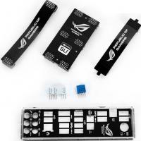
Contents of delivery
The delivery set corresponds to the status. It contains everything you might need when assembling a system, and several pleasantly useful additions: a “Do Not Disturb” sign, a sticker with the ROG logo, and convenient stickers for marking SATA cables. In addition, the following are included in a separate black box:
- user guide;
- DVD with software;
- plug for the rear panel of the case;
- six SATA cables;
- CrossFire bridge;
- SLI bridge (3-Way SLI);
- regular SLI bridge;
- USB-AA cable for ROG Connect;
- two Q-Connectors.
⇡ Appearance and supported interfaces


ASUS Crosshair V Formula-Z motherboard
The board is made of elements in black, red and white. More precisely, not quite red: this color is closer to alizarin or crimson, which, combined with the “matte” look, looks very nice and expensive.

Number of PCB layers
The PCB consists of eight layers, which is normal for a board of this level.

Memory slots
The traditional color division of memory slots helps in the distribution of modules across channels. There are latches only on one side; the memory is secured easily and securely. This is what the user sees. But there is also something that is hidden from view - the changed topology of the printed circuit board. However, if you look closely, you can see an ornate labyrinth of tracks on the top layer of the printed circuit board.

As can be understood from the illustration above, the essence of T-Topology is an equal length of tracks from the processor to the memory modules, which should have a positive effect on the resulting maximum achievable memory frequency. In total, you can install four DDR3 SDRAM sticks, but due to their proximity to the processor socket, two of them may be blocked by the processor cooler. As usual, there are two ways out: do not use memory with high heatsinks or look for a cooler of a suitable size. The height of the VRM cooling system and the northbridge imposes virtually no restrictions.
To receive power, the board has as many as four connectors. The 24-pin ATX connector is unremarkable, except that it is located quite conveniently. For additional power supply to the processor, 8- and 4-pin headers are used. You can use only one of them, but this feature is unlikely to be needed by the buyer of the board, because the purpose of purchasing it is high results in everything.
For the same purpose, a four-pin molex is installed on the board, designed to meet the needs of devices installed in PCI-e slots. In particular, it is recommended to connect power to the EZ Plug when installing several video adapters.

ProbeIt pads, multimeter connection
The space between the edge of the board and the ATX power connector was occupied by contact pads for measuring voltages. The distance between the points is small, but the GND contacts are well placed on both sides. It would be absolutely wonderful if the contact points were made flat and of a larger area. These (small and convex) clamps slide off at the slightest shock.
Since the equipment tends to heat up, eight fan connectors are distributed throughout the motherboard. All have four contacts and can control the rotation speed using pulse width modulation or voltage variation. The engineers did not forget about the needs of owners of dual-propeller supercoolers - two of the eight connectors are intended for the processor cooling system. It is impossible to set the speed for each of the “wind blowers” separately, but it is possible to do this for three groups: CPU fans (two), case fans (three) and additional fans (the remaining three).

Northbridge 990FX

Southbridge SB950
All capabilities of the board are provided by a combination of the 990FX north bridge and the SB950 south bridge. The total number of PCI-e lanes is 42, but four of them are spent on the A-Link Express III inter-bridge interface. Compared to the previous “formula” (the one without Z in the name), no changes occurred - new logic sets from AMD were not released.

PCI-Express slots
It was decided to abandon outdated PCI on ASUS Crosshair V Formula-Z. Due to the freed up space, it became possible to increase the distance between the three upper PCI-e x16 slots. This solution allows the use of graphics accelerators with massive cooling systems.

PCI-e switches ASM1440
The lines are switched by four eight-channel ASM1440 switches designed to work with PCI-e 2.0. In accordance with the instructions, the following speed mode options are possible for full-size slots:
- only the first or third slot is occupied, one video card operates in PCI-e x16 mode;
- The first and third slots are occupied, video cards operate in x16/x16 mode.
- the first three slots are occupied, the lines between video cards are distributed as x16/x8/x8.
When using the second and third options, you must not forget about connecting additional power to the EZ Plug connector. The first option is notable for the fact that when installing a single card in the third slot, the transfer speed does not drop, that is, you get the opportunity to place the hottest components (central and graphics processors) away from each other.
It is not entirely clear why the capabilities of the 990FX northbridge to create multi-GPU configurations were not fully used. Perhaps ASUS decided that the current generation of AMD processors is not able to load four graphics adapters with work. It is also likely that the speed formula x8/x8/x8/x8 would not provide top-end video cards with the necessary bandwidth, and solutions in the mid-price range are unlikely to be used to create a “quartet”.
The lower PCI-e x16 slot has four data lines at its disposal, so it is more logical to classify it as a “peripheral” slot along with two PCI-e x1 slots nestled between the first and third full-size slots.

Such a system bus generator ICS 9LPRS477DKL

PCI-e ICS 9DB403DGLF Clock Generator
Between the first and second PCI-e x16 microcircuits 9LPRS477DKL and 9DB403DGLF from ICS were found. The first sets the base frequency, the second sets the PCI-Express frequency. SetFSB fans, take it into your arms.

SATA connectors
To the right of the southbridge heatsink are eight SATA3 connectors. They are placed parallel to the motherboard, so even a long video card hanging over them will leave the ability to freely connect/disconnect drives.

SATA 3 controller ASMedia ASM1061
The top six ports (in the normal position of the motherboard) are serviced by the chipset, the two below them are serviced by the ASMedia ASM1061 controller. There is no color division, but the necessary markings are present. In addition, in order not to get confused which cable is connected to which drive, you can use the convenient included stickers. Another ASM1061 is used for eSATA connectors on the rear panel of the motherboard.
Since we touched on the topic of data transfer, let's see how another serial interface is implemented on the board - USB. Without additional accessories, you can connect 12 devices with this interface to the board, four of them are of the third version. If you look for external ports, USB 3.0 will increase by two more, and USB 2.0 by four.

USB 3.0 controller ASMedia ASM1042
The south bridge is responsible for all two-zero ports; the organization of the SuperSpeed USB interface is entrusted to three ASMedia ASM1042 chips located near the ports.

Intel 82583V Network Adapter
A representative of a competing camp was seen among the components. The fact of its presence is even shown on the box: on the board for AMD processors there is an Intel 82583V gigabit network controller. It is chosen for its qualities such as high throughput, connection stability and low CPU load.

Super I/O chip
The commonly used ITE IT8728F chip is used to monitor system performance, control fans, and maintain the combined (mouse/keyboard) PS/2 port.

ROG Connect Controller
It is perhaps worth mentioning the abundance of relabeled microcircuits. We know the purpose of one of them (iROG P128V1) - it is responsible for implementing the ROG Connect function, which will be discussed in more detail.

TurboV Processing Unit
Also on the board (under the southbridge heatsink) there is an exclusive TPU chip responsible for automatic overclocking. The results of its collaboration with AI Suite II will be discussed further.
To control the boot stages, the motherboard has two tools.

LED indicators of loading stages
The first is quite crude - four LEDs that light up and go out as certain stages of the system check pass. In case of an error, the corresponding “light” will not go out.

FPGA ALTERA EPM3032A
The second is the POST code indicator - a tandem of ALTERA EPM3032A and a seven-segment display.

Rear connector panel
The rear interface panel is literally occupied by USB ports. Boards for LGA1155, which have several video outputs, are significantly behind in this aspect. A total of 12 ports are located here - the “stacks” of the second and third versions of the interface alternate in pairs. There was also room for a pair of eSATA and a PS/2 keyboard/mouse combo. The sound is represented by an optical output and six gold-plated “jacks” from the inside. There are also two buttons: Clear CMOS and ROG Connect.
Internal connector strips
The lower part of the motherboard is used for internal connectors. When viewed from left to right (ignoring the buttons, switches and fan contacts) we will see: a front panel audio connector, an S/P-DIF output, a TPM connector, the beginning of a Thunderbolt connector (an additional board will be required), a couple of USB headers and contacts for connecting buttons / front panel indicators. Next to the latter there are a couple more contacts, to which you can connect some kind of case button (for example, Reset, if there are no others). Clicking on it will be equivalent to clicking on DirectKey.
Let's take a closer look at the controls located on the board. The DirectKey mentioned above can be used to turn on the system and then automatically enter the BIOS - eliminating the need to “slot” the Del or F2 keys. If the system was turned on, the first press of the button will turn it off, the second will still provide entry into the BIOS. The nearby FAST_BOOT switch allows you to skip POST, speeding up system startup (especially important for Windows 8).

Overclocker's Corner
The remaining buttons are located in the upper right corner, next to the RAM slots. The largest button, Start, turns on the system. In addition, when the power is connected, the LED built into it lights up. It is impossible not to notice it, so the hand itself will reach for the power supply switch to de-energize the board before replacing components. Next door is a Reset button, the purpose of which also does not raise questions. Another small button - GO_BUTTON - activates the MemOK! function during boot, and while the system is running, activates the profile recorded in the corresponding BIOS section. A little further away, the switches found their place: LN2 and its dependent SLOW_MODE. If you move the jumper, the motherboard gets the opportunity to counteract the “cold bug”, and the accompanying switching of SLOW_MODE to the ON position will force throttling. The combination of these two features will greatly simplify life for fans of extreme overclocking.

SupremeFX III audio system
We should also talk about the sound subsystem. It’s about the subsystem, because the entire lower left corner of the board was “protected” for it. ASUS engineers have done a lot of work to reduce interference from high-frequency digital components of the main part of the board.


Implementation of RedLine backlighting
Insulation in the horizontal plane is made using the so-called “red line”, which, to fully comply with its name, is beautifully illuminated from the back of the board with several LEDs (unpainted PCB without metal allows light to pass through). But this is only the visible part of the iceberg: the path from the DAC to the connectors is isolated using copper layers at the top and bottom (in the vertical plane). The audio codec itself - Realtek ALC898 - is also protected from EMR using a metal shield. To ensure that high-impedance headphones do not lose part of the sound picture, there is a huge 1500 µF capacitor at the point where the power supply of the audio path is connected.

Motherboard backlight operation
The backlight LEDs can be turned off, but will you be able to do it?
⇡ Power subsystem

PWM controller of the processor power supply system
The processor power supply system is stated as digital 8+2-phase. The PWM controller is a microcircuit relabeled in ASP1000C. A leisurely search and analysis gives reason to assert that this name hides the eight-phase CHL8328 from CHiL Semiconductor.

Doubler driver and low-side transistors
How then are the ten phases obtained? On the back of the motherboard, under a layer of thermally conductive material and a metal plate, all the drivers, also relabeled, are hidden, now called ASP0A13. If you count their number, you can come to the conclusion that there are half as many real power phases, and these same unidentified microcircuits double them.

Processor power supply
The upper side uses 4955N transistors, and the lower side uses 4937N transistors from ON Semiconductor. The “bottleneck” of each power phase will be the 4955N, rated for currents up to 48 A (each of the 4937Ns is capable of handling currents up to 70 A). In any case, eight such phases will be quite enough even for extreme overclocking using liquid nitrogen or helium, and even more than enough for everyday use. Since the low-side transistors divide the load in half, the drivers located on the back of the motherboard make do with small aluminum plates weighing six and eight grams.


Radiators for board cooling system
The upper radiator is disproportionately larger in size and weight (about 215 g), since it is designed to remove heat from the main power part of the power supply system and the north bridge at the same time (the VRM and NB radiators are combined using a heat pipe). The Southbridge is cooled by its own massive (71 gram) radiator. All components of the motherboard cooling system are attached with spring-loaded screws, which ensures confident pressure and secure fixation.
The capacitors used are exclusively polymer capacitors with a capacity of 820 uF: nine for the CPU cores, a pair for the CPU/NB and cache.

RAM power supply system and its controller
The RAM power supply system does without radiators, since the load on it is disproportionately less. It consists of two phases controlled by an ASP1103 PWM controller (oh, those fans of relabeling: the real name could not be found). Already known 4955N transistors were used, a pair per phase. They didn't skimp on the capacitors here - there are six of them, each with a capacity of 560 µF. A couple more similar ones are installed in the power circuit of the north bridge. By the way, inductors with ferrite cores in metal cases are used everywhere.
Introduction
Even before the release of new processors for the AM3+ socket, ASUS decided to introduce several updated models of motherboards. And since the system logic sets remained the same, the manufacturer had to independently bring all products into line with modern consumer demands. To begin with, the number of modern interfaces, such as USB 3.0 and SATA 6 Gb/s, was increased. Then some proprietary features are added that are used on other motherboards.
In particular, the ASUS Crosshair V Formula motherboard underwent such modernization. This is the company's most advanced solution for the AM3+ platform, belonging to the ROG (Republic Of Gamers) series. To highlight the updated model, the letter “Z” was added to its name. All that remains is to test the result of such a modification and find out how much the consumer properties have improved. Meet - ASUS Crosshair V Formula-Z.
Packaging and accessories
The packaging is made in the traditional style for the entire ROG line.

The medium-sized box is made in red tones. On top you can find a plastic handle for easy transportation.

Compared to its predecessor, the name of the model has changed on the front side - the letter “Z” has been added. In addition, a support icon for the Windows 8 operating system appeared at the bottom.

Otherwise, all emblems and styling remained unchanged. As before, the front part is the cover.

Underneath is a transparent plastic window through which you can see the motherboard itself. On the back of the cover there is a description of some of the new technologies and functions, as well as the software included with the board. There are also several inserts with photographs.

Nearby is the product specification and a diagram of the rear panel connectors and buttons. Inside the package there are two black cardboard boxes. In one of them, under a transparent plastic cover, the motherboard itself rests.

The other contains the delivery kit.

It is divided into four parts by a special separator. Two of them are intended for information media.

- User Guide (user's manual for the motherboard);
- Card on the doorknob with the inscription “Do not disturb”;
- Set of stickers for identifying system cables;
- DVD with drivers and software for various operating systems.
- Sticker on the case with ROG symbols.
And on the right are the accessories.

- Six SATA 6 Gb/s cables;
- Flexible bridge SLI;
- Rigid bridge 3-WAY SLI;
- CrossFire bridge;
- Q-Connector connector kit;
- Plug for the rear panel;
- USB to USB cable for implementing ROG Connect technology.
Taking into account modern trends, ROG Connect technology could be implemented without a cable, for example, using Bluetooth or Wi-Fi.
Board design and features
At first glance, it is difficult to notice any changes compared to its predecessor, which has already been reviewed in detail.

However, we have a completely different board in front of us, despite some seemingly similarities.

First of all, we can note the dimensions - it is 305 x 244 mm, which corresponds to the ATX standard. In addition, the color palette, number and location of most slots are the same. For example, the power supply is organized in a similar way. Here it is also carried out through the main 24-pin and two additional 8- and 4-pin connectors.


In addition, you can find one Molex connector on the board. It is designed to provide additional power to the PCI-e bus. For a top-end motherboard, such a set of connectors does not look unusual.
To support DDR3 memory, there are four slots in red and black. Some of them can be covered by a large cooler like the Noctua NH-D14. However, almost all boards running AM3+ suffer from this problem, so you need to take this point into account and use either a CBO with high heatsinks on memory modules, or a large cooler, but without cooling on the brackets.

The manufacturer declared support for DDR3 1066/ 1333/ 1600/ 1866/ 2133 (overclocking)/ 2400 (overclocking) MHz operating modes with a standard voltage of 1.5 V. Such frequencies will not surprise anyone, because the Intel LGA 1155 platform has already approached the 3000 MHz mark. The maximum allowed volume is 32 GB, for example, four 8 GB modules.
The processor power supply circuit is made according to the 8+2 phase formula, it is almost similar to that used in the ASUS Sabertooth 990FX R2.0.

In this case, the power elements are located on both sides of the board.


On the reverse side there is a part of transistors and drivers marked ASP0A13.


The ASUS Crosshair V Formula-Z is equipped with previously seen inductors in ferrite housings and solid-state capacitors.

Not far from the memory slots there is another PWM controller labeled Digi+ ASP1103.

The cooling system, which removes heat from the power elements, consists of several parts. On the reverse side there are two aluminum alloy plates for this purpose.


Along their edges there are steel guide bushings that fit into special holes on the printed circuit board. A gray thermal rubber band with a thickness of about 1 mm is used as a thermal interface. On the front part there is a large radiator, which consists of three sections.


One of them removes heat from the upper group of transistors, the other from the side group, and the third from the north bridge. All parts are connected together by a heat pipe that runs through each of them. The radiators are rough to the touch, but about the support for CeraMIX technology! nothing is said here. On those of them that remove heat from transistors, a light green thermal pad about 1 mm thick with thin threads is used as a thermal interface, which allows the heat-conducting material to keep its shape. They are fastened with four spring-loaded screws on the front side.

The chipset heatsink uses a pink “thermal cup” as a thermal interface.

Along the perimeter of the aluminum heat sink there is a protective frame made of soft porous material. This radiator is attached from the reverse side using two spring-loaded screws of a different type.

Another heat dissipation device is located on the AMD SB950 southbridge. A plate with the ROG emblem and the manufacturer’s logo is attached to the front part.


Under the radiators there is a logical connection of AMD 990FX + SB950.


Both microcircuits have already been studied inside and out, and some could already memorize their specifications. For example, everyone knows that the north bridge provides forty-two PCI-e 2.0 lanes. Therefore, the presence of four PCI-e x16 slots does not seem surprising. After all, theoretically, eight lines can be supplied to each of them.

But here the scheme is somewhat different. The top one always gets sixteen lines, and the bottom one always gets four. The remaining ones divide another sixteen lines depending on the number of installed video adapters, forming two formulas x16+x8+x8 or x16+x16+x0. SLI and CrossFireX multi-graphics modes are supported. In addition, the board has a pair of PCI-e x1 slots.
To support storage devices and drives, the board provides eight SATA 6 Gb/s ports.

Six of them are implemented by a controller integrated into the south bridge, and two more are implemented by a separate Asmedia ASM1061 chip, which is soldered nearby.

Another similar chip is located near the rear panel, where you can find two eSATA ports. In the lower right corner there is a connector for connecting buttons and indicators of the case.

To the left of it is the Direct Key button, which allows you to enter the BIOS.


In addition, there is another connector of this standard for connecting two devices. To implement it, we again had to use Asmedia ASM1042, already the third on this board.

The block is soldered close to the main ATX power connector.
The lower left corner and part of the same edge are dedicated to the audio codec. Its boundaries are marked by a special strip about 2 mm wide, which is also a printed circuit board, but without metallization layers, so it is visible through. On the reverse side, along the perimeter of this border, red LEDs are wired. When power is applied to the board, they begin to emit light and illuminate this strip.

Just above is the ITE IT8721F I/O controller.

The installed network adapter cannot be called ordinary for motherboards on the AMD platform, since it is represented by the Intel WG82583V chip.

In the upper right corner you can find some semblance of a control unit.

It includes three buttons, a switch, a jumper and a dual seven-segment indicator for loading POST codes.

Power and Reset are equipped with LEDs and are illuminated simply when voltage is applied to the board.
Nearby is the GO Button, which has two purposes. First, it includes the MemOK! feature. Secondly, it allows you to activate a profile specially recorded in the BIOS. The LN2 jumper puts the board into extreme overclocking mode, and the Slow Mode switch launches the function of the same name, which helps improve stability.
In addition, there are many different LEDs soldered on the board. A group of four red lights is located next to the main ATX power connector.

Each of them is responsible for initializing the main components of the system. Nearby there are areas for measuring voltage on various buses.

Another yellow LED is installed a little lower, behind the SATA connectors.

It shows activity while working with the hard drive. The remaining connectors, as well as their location, can be seen in the diagram attached below.

Now let's see what's on the back panel.

- One PS/2 connector for connecting a keyboard or mouse;
- Four USB 3.0 connectors;
- Eight USB 2.0 connectors;
- Two eSATA connectors;
- One gigabit RJ-45 network connector;
- Six minijack audio connectors;
- One optical S/PDIF Out connector;
- BIOS Flashback button;
- ROG Connect switch.
Specifications
| Supported processors | AMD AM3+ FX / Phenom II / Athlon II / Sempron 100 Series |
| System bus, frequency | Hyper Transport 5.2 GT/s |
| System logic | AMD 990FX + SB950 |
| RAM | 4 x 240-pin DDR3 DIMM, dual-channel mode, up to 32 GB at 1066 / 1333 / 1600 / 1866 / 2133 (overclocked) / 2400 (overclocked) MHz |
| Expansion slots | 4 - PCIe 2.0 x16 2 - PCI 2.2 |
| Multi-GPU support | SLI, 3WAY-SLI, CrossFireX, (x16+x8+x8). |
| SATA/RAID support | 6x SATA 6.0 Gb/s ports – AMD SB950; RAID 0, 1, 5, 0+1, JBOD; 2x SATA 6.0 Gbit/s ports – Asmedia ASM1061; RAID 0, 1, 0+1 |
| IDE and eSATA support | No; 2x eSATA 6.0 Gb/s - Asmedia ASM1061; |
| Net | 1x Intel WG82583V |
| Audio | Realtek ALC898 – 8-channel HD audio codec |
| USB 2.0 | 8+4x USB 2.0 (AMD SB950) |
| USB 3.0 | 4+2x USB 3.0 (3x Asmedia ASM1042) |
| IEEE-1394 | No |
| System monitoring | ITE IT8721F |
| Motherboard power | ATX 24-pin, 8-pin ATX 12V, 4-pin ATX 12V |
| Rear Panel Connectors and Buttons | 1x PS/2 keyboard or mouse 8x USB 2.0/1.1 4x USB 3.0 2x eSATA 1x S/PDIF Optical Out 1x RJ45 6x 3.5mm Jack 1x BIOS Flashback 1x ROG Connect |
| Proprietary technologies | RC Diagram RC Remote RC Poster GPU TweakIt 8+2 phase power design 2-phase Memory power design ROG BIOS Print GPU.DIMM Post GameFirst iROG Extreme Tweaker COP EX (Component Overheat Protection - EX) ASUS C.P.R.(CPU Parameter Recall) ASUS EPU TurboV Core Unlocker AI Suite II AI Charger+ USB 3.0 Boost Disk Unlocker ASUS Fan Xpert ASUS O.C. Profile ASUS CrashFree BIOS 3 ASUS EZ Flash 2 ASUS MyLogo 3 ASUS Q-Shield ASUS Q-Code ASUS Q-LED (CPU, DRAM, VGA, Boot Device LED) ASUS Q-Slot ASUS Q-DIMM ASUS Q-Connector |
| Dimensions, mm | 305 x 244 |
| Form factor | ATX. |
BIOS Features
You can view the BIOS of the ASUS Crosshair V Formula-Z board using the video below.

I would like to see this on all models. Or, at least, to be able to set this page as the start page, for example, such a function is available in the BIOS of ASRock motherboards. The ROG series differs from other models in a different color design of the BIOS graphical shell. Otherwise, there is no fundamental difference, so it makes no sense to describe all the subtleties in detail. I’ll just note that at the bottom of the Extreme Tweaker page there are several points dedicated to changing the voltage on components in the following ranges:
- CPU Manual Voltage - (from 0.67500 to 2.07500 V in steps of 0.00625 V);
- CPU/NB Manual Voltage - (from 0.50000 to 1.90000 V in steps of 0.00625 V);
- CPU VDDA Voltage - (from 2.20000 to 2.60000 V in steps of 0.00625 V);
- DRAM Voltage - (from 0.86000 to 2.13500 V in steps of 0.005 V);
- NB Voltage - (from 1.10000 to 1.25000 V in steps of 0.00625 V);
- NB HT Voltage - (from 1.20000 to 1.40000 V in steps of 0.00625 V);
- NB 1.8V Voltage - (from 1.80000 to 2.80000 V in 0.005 V increments);
- SB Voltage - (from 1.10000 to 1.80000 V in steps of 0.005 V).

DRAM Driving Control.


And Digi+ Power Control.


Next comes the Advanced tab. There are twelve links on this page.

CPU Configuration.

North Bridge Configuration.

South Bridge Configuration.

SATA Configuration.


CPU Core On/Off Function.

Onboard Devices Configuration.


iROG Configuration.


Voltage Monitor.

Temperature Monitor.

Fan Speed Monitor.

Fan Speed Control.
 Cooler: Noctua NH-D14;
 Overclocking and thermal conditions
The first overclocking experiments were carried out during the preparation of material dedicated to the announcement of Vishera processors. Using the same link you can see the test results, since it was carried out on this board. Then I decided not to take risks and not raise the voltage on the FX-8350 above 1.45 V.
This time the CPU voltage was increased in order to get closer to the cooling system limit. More precisely, to a regime in which it will no longer cope with the increased heat generation and there will be no stability. And if 1.45 V is enough to reach a frequency of 4700 MHz, then increasing it by just 100 MHz requires 1.5 V on the cores and 1.35 V on the CPU/NB. And to achieve 4.9 GHz, we had to raise the voltage to 1.525 V, which is already on the verge of the cooling system’s capabilities.

The processor continues to load the system up to 5100 MHz, but there is no longer stability. As for the system bus, the result could not be improved; it was still 300 MHz. NB and HT bus frequencies have been increased to 2600 MHz. After flashing the latest BIOS 0806, the memory worked a little better. We managed to run it at a frequency of 2400 MHz with timings of 11-12-12-30-1T. Monitoring the processor's performance is possible using the AMD OverDrive utility.

It displays values for each of the cores, but the voltage is incorrect. When overclocked and under load, the processor easily manages to exceed 80°C even when using a cooler such as the Noctua NH-D14.
How do power elements and logic chips feel during overclocking? To do this, you need to look at the temperatures of all radiators.
| System bus, frequency | Simple (standard/overclocked) |
|
| Upper radiator | 44/53 | 51/57 |
| Side radiator | 43/51 | 50/57 |
| Northbridge heatsink | 41/51 | 48/56 |
| Northbridge heatsink | 44/45 | 44/45 |
There are no prohibitive indicators. This is partly due to the good ventilation of the case. But the processor cooler actually emits heat like a stove. The last time I saw something like this was only on an overclocked Core i7-3930K.
Built-in sound
The audio codec is represented by the Realtek ALC898 chip. Listening was carried out using Sennheiser HD201 and Zalman ZM-RS6F headphones and Microlab PRO 1 acoustics.
Despite some semblance of isolation and the introduction of “magic” capacitors, the sound cannot be said to reach the level of Creative X-Fi or ASUS Xonar cards. Yes, the sound is clear, without extraneous noise, but things are still not good with low frequencies, positioning in games and immersion in the environment when watching movies. Although the sound solution is designed for gamers, in my opinion, the Realtek ALC898 codec is least suitable for these purposes. Therefore, the miracle did not happen.
Conclusion
What do we get as a result? This question can be answered only by thinking about something else: who is this board intended for? Yes, even a schoolchild will understand that this is for gamers - fans of computer games. In any case, this follows from the name and positioning of the Republic Of Gamers line itself. If this is the case, then the ASUS model does not look in the best light.
To begin with, not every fan of running in virtual worlds is comfortable with overclocking, and this board leaves no compromises. Only manual overclocking and only with an eye to achieving maximum results. There are also automatic presets, but they are not very effective and only slightly increase the frequency. Using an Intel network controller is nothing more than a marketing ploy, otherwise half of the motherboards on the LGA 1155 platform can be classified as gaming. And what fundamentally changes? Ping remains unchanged, the only difference is that QoS works more efficiently with the same channel bandwidth.
Maybe the sound has become better? After all, Supreme FX III is also insulation from the main printed circuit board. Everything is true, but Realtek ALC898 is still installed here. It reproduces music well, but does not cope well with large scenes. In addition, probably not all professional gamers will be satisfied with the AMD platform. Are there many games that can use all eight cores of the AMD FX-8350 processor (for the Sempron 145, the purchase of such a board is very doubtful)? So little by little, at every point, you understand that the motherboard is not intended for gamers.
The ASUS Crosshair V Formula-Z motherboard is dedicated to overclocking, benchmarks, and records using extreme cooling. This is evidenced by the device’s instrumentation, designed to simplify the overclocking process as much as possible specifically with cryogenic cooling. However, not everything is so smooth here either. For example, the processor power system is no different from that on the ASUS Sabertooth 990FX R2.0, which costs much less, which means it will often be seen in such photographs.

So it turns out that the new product is good for everyone, but is suitable only for a narrow audience of buyers.
Pros:
- Four PCI-e x16 slots;
- Good overclocking capabilities;
- High-quality element base and execution;
- Support for the most modern interfaces;
- Special modes for extreme overclocking;
- Many LED indicators for diagnostics;
- Support for multi-graphics technologies: CrossFireX and SLI.
- There are no obvious ones.
First sourcehttp://www.overclockers.ru/lab/50543/Obzor_i_testirovanie_materinskoj_platy_ASUS_Crosshair_V_Formula-Z.html
Chapter: ,
Source: 3DNews |
This +SB950 chipset motherboard for avid gamers and computer enthusiasts offers almost maximum comfort for building a powerful system with AMD Bulldozer processors and more. The overclocking potential of the board is impressive.
My dear mother!
You, young princess!
Look there:
Father is coming here.
A.S. Pushkin. The Tale of Tsar Saltan
We simultaneously received two fresh top-end motherboards for the AMD platform on the 990FX chipset - both from Taiwanese manufacturers related by blood: Crosshair V Formula and ASRock Fatal1ty 990FX Professional. Both boards are expensive (no joke!) gaming products, designed primarily for installing multiple video cards, overclocking (reasonable or extreme), creating anything and everything you can afford with a PC on AMD processors, and, of course, for assembling a powerful gaming machine that can give the gamer both pathos and the strength to become a real “father.”
Ai Charger+, etc.
Current average retail price, rub.
The board is equipped with high-quality processor and memory power stabilizers: two-phase on the memory and 8+2-phase on the processor. The latter's power switches are covered by a relatively large, although not gigantic, heatsink, connected by a heat pipe to a heatsink on the northbridge of the chipset. All heat dissipators are secured to the board with strong screw connections. Of course, only solid-state Japanese capacitors with a long MTBF are used here.

On the left in the photo under the heatsink you can see the northbridge of the chipset, on the right is the VRM Digi+ EPU chip
To power the processor, this board uses not only the usual 8-pin ATX connector EATX12V, but also an additional 4-pin EATX12V_1. The latter can be useful in the case when, as a result of unrestrained overclocking of the processor with a significant increase in the supply voltage, its power consumption significantly exceeds the power supply limit on the main line (usually about 200 W: +12 V multiplied by the line current limit of 18, 20 or 25 A) . It's no secret that for top AMD processors this situation during overclocking is not uncommon. In this case, the second power line of the processor can almost double its electrical power reserve.

Second CPU power connector and Digi+ EPU VRM controller
The memory slots do not have bottom module latches. This is justified in the case when the installed video card blocks such latches, but there is nothing like that here - the gap between them is decent, so there was no need to “save on latches.” Although even without them, the modules fit in the connectors quite tightly. However, those who often change memory (for example, on test benches or overclocking benches) will appreciate the ability to “click the locks” half as often.

The board can not only increase the supply voltage on all main components (see below), but also has special ProbeIt pads for monitoring voltages on the CPU, memory, HT bus and northbridge using an external voltmeter. In addition, special Voltiminder LEDs indicate the current voltage status of the CPU, memory and chipset, which can help with overclocking.

ProbeIt sites
There are only six slots for expansion cards on the Crosshair V Formula. The placement of the seventh (for example, PCIe x1) was prevented by the heatsink of the northbridge of the chipset, which was unconventionally shifted to the left edge of the board (however, this was also the case with the Crosshair IV Formula; the slot configurations of these two boards were almost identical, only there was no official support for SLI). Let's hope that the absence of a seventh slot is not critical for gamers, especially since the board has one PCI Express x1 and one PCI slot each, and the other four are PCI Express x16 connectors. The top (first) and third of them can work in x16 mode, the bottom one always works as x4, and the second one from the top can work either as x8 (then the third PCIe x16 slot also switches to x8 mode) or as x1 (if the third one functions as x16 ). This flexibility in configuration allows you to optimally create systems with several video cards: three “double-decker” cards will work with x16+x8+x8 buses (though covering all other slots for expansion cards), and two will work in x16+x16 mode, leaving PCI and PCIe x16(x1) slots are available, and there will be sufficient clearance between the video cards for good ventilation or installation of “two and a half storey” video cards (the advanced cooling systems of which are thicker than the reference ones). When installing two or more video cards, the manufacturer recommends connecting additional power for the PCI Express bus from the Molex connector of the power supply to the EZ-Plug connector of the motherboard (this is a 4-pin Molex).
The south bridge of the chipset is covered with a large heatsink. Next to it are 7 SATA 6 Gb/s ports (6 chipset and one from the ASMedia controller), a paired USB 3.0 connector for the front panel and two more paired USB 2.0. This expensive board does not have FireWire ports (Crossfire IV Formula had them!), IDE, FDD and COM ports - apparently, gamers and professional overclockers do not need them.

SATA connectors and paired USB 3.0 for the front panel
And there is only one gigabit network controller, and on an Intel chip, and not built into the AMD chipset.

The Super I/O chip is the popular ITE IT8721F, and the audio codec is nowhere more “popular”: the 8-channel Realtek ALC889.

True, it has an “X-Fi 2 SupremeFX” sticker three times larger than the chip itself, indicating that the board supports software implementations of many popular gaming audio technologies: EAX Advanced HD 5.0, THX TruStudio PRO, X-Fi Xtreme Fidelity, Creative ALchemy and etc.

With them, it hardly makes sense to buy a separate sound card for games. An optical S/PDIF output on the rear panel (and an electrical one on the board itself) will allow you to “purely” connect to good acoustics, especially since the analog audio path of this board, as we will see below, leaves much to be desired.

The back panel of the board is well-stocked with connectors, but not to the maximum. There is one eSATA, one RJ45, six audio jacks (with optical S/PDIF), a PS/2 combo (for keyboard or mouse), a clear CMOS button (sometimes useful when overclocking), as well as 12 USB ports, four of which are version SuperSpeed (USB 3.0; they are traditionally blue). One USB 2.0 port is highlighted in white - a ROG ThunderBolt card can be connected to it if necessary. In its absence, the port can serve as a regular USB 2.0 if the ROG_Connect switch located near it on the board is set to the appropriate position.


The Crosshair V Formula board is very overclocker friendly. It is characterized not only by the features mentioned above, it has conveniently illuminated Start and Reset buttons, as well as an O.C. button, which allows you to overclock the computer with one click (however, overclocking will be far from the maximum possible). These three buttons are located at the very bottom of the board under the PCI Express slot, and when using a motherboard with two or three video cards, their operational accessibility may raise questions; it would be better to move them to the “near” corner of the board.

In addition, in the upper right corner of the board, above the memory slots, there is a “Go” microphone, which allows the system to start with the settings reset (the button is useful when overclocking), and the restart parameters can be set in the corresponding item of the BIOS Setup menu, see screenshot .

Again, in the case of the system unit this button will be difficult to access, so it is intended rather for open overclocking or test benches.
Finally, this board is very rich in fan connectors - there are already eight of them, all of which have 4-pin connectors (electrical PWM control is provided only for the processor cooler). Three connectors are located at the top of the board (two of them are for the CPU cooler), one is near the memory, another is near the rear panel of the board, and three are at the very bottom of the board (“front” and “rear”). In general, it is completely convenient to connect fans. By the way, you can control the rotation speed through the BIOS Setup menu for most of them, see below.
Oh yes, this board also has three 2-pin connectors for external thermistors - near the memory, near the north bridge and at the very bottom under the PCIe slots. Thermistors are purchased by the user independently, and in the BIOS Setup menu of the board they can not only be “monitored”, but also serve to automatically control the rotation speed of the three corresponding system fans! This is potentially very convenient and eliminates the need to purchase and install an appropriate rheobass in the case.

Control of several system fans from thermal sensors via the board's BIOS Setup menu
Settings menuBIOS Setup of the boardCrosshair V Formula
Sewn into the 32-megabit AMI UEFI BIOS chip of this board, traditionally for top-end motherboards, it is very rich in settings - regular and fine. Most of the functions are clear from the screenshots below, especially since the beautiful graphical, “under the mouse” interface of the BIOS Setup menu is quite well translated into Russian (although, out of habit, sometimes you have to wonder what this or that Russian term actually means).

Therefore, we will explain only the most interesting, in our opinion, points.


The Core Unlocker feature, if you're lucky, allows you to unlock disabled cores in Athlon and Phenom processors (however, the system may become unstable). Unfortunately, this function does not work on AMD FX processors, and it will not be possible to turn a 4-core processor into a 6- or 8-core processor. But the “Processor Core Activation” function will allow, if necessary, to exclude one or more cores from the processor.

An interesting feature for the USB 3.0 controller is the battery recharging function, which allows you to increase the output current through the power line (+5 V) of the corresponding connectors.

Digital audio output can be switched between S/PDIF and HDMI modes.


The Voltiminder LEDs on the board can be reassigned to indicate voltage levels: for CPU LED this can be the voltage on the CPU, memory controller or CPU VDDA, for NB LED this can be the northbridge itself (main power), its 1.8 V power supply or the PCI bus Express, for SB LED – itself or the HT bus, and for DDR LED – DDR or VDDR voltages.

The board's BIOS Setup menu controls the levels of 10 supply voltages, including the CPU core voltage and many internal,

as well as the temperature of five points (three of them using external thermistors purchased separately), and for them you can set the maximum permissible operating value in the range from +70 to +100 degrees Celsius.

The rotation speed of all eight fans, which can be connected directly to this board, is also monitored!

Control of the rotation speed of the Carlsons is implemented in a separate menu item and only for five fans (or rather, six, since two processor fans are controlled synchronously). For a processor cooler, you can select the type of control (PWM, that is, pulse-width modulation, or DC, that is, power supply voltage) and the degree of regulation (three presets or manually, see the screenshot above), with a separate setting of the minimum fan speed. For a case fan (without the possibility of PWM control), three presets or manual adjustment are also allowed, as well as setting the minimum speed.


For three optional system fans, which can be controlled “from” external thermistors (OPTFAN1-3), here you can set both a constant rotation speed (from 40% to 100% in 10% increments in Duty Mode), and smooth speed control from temperature of the corresponding thermistor (User Mode). In the latter case, the minimum speed is achieved when the sensor temperature is set in the range from 25 to 40 degrees in steps of 5, and the maximum speed is achieved when the thermistor reaches a temperature set in the range from 60 to 90 degrees in steps of 10 (see two screenshots above). Let us repeat, this is a very convenient function for using the board in a case, since it allows you to replace a rather serious (and expensive) external bass.


The richest settings item in Ai Tweaker deserves a separate discussion.


We present the ranges of changes in the operating values of numerous quantities (frequencies and voltages) in the summary table.
Adjustment rangesfrequenciesAndstresson the menuBIOSBoard setup
| Parameter | Range of change | Change step |
|---|---|---|
|
Changing the CPU multiplier |
Depends on CPU |
|
|
BCLK/PEG frequency (CPU reference frequency) |
||
|
PCI Express Bus Frequency |
||
|
DDR3 memory frequency |
||
|
CPU NB frequency (memory controller in CPU) |
1600-6200 MHz |
|
|
HyperTransport bus frequency |
||
|
CPU VRM frequency |
||
|
CPU core supply voltage |
||
|
CPU Memory Controller Supply Voltage |
||
|
CPU voltage VDDA |
||
|
DDR memory bus supply voltage |
||
|
Memory voltage VDDR |
||
|
DRAM reference voltages Vrefdq, Vrefca, VrefcaCPU |
||
|
Chipset northbridge supply voltage (NB) |
||
|
HyperTransport bus supply voltage |
||
|
Supply voltage NB 1.8V |
||
|
PCI Express bus voltage (VDD PCIE) |
||
|
Southbridge voltage (SB) |
1.113 - 1.802 V |
The rich settings for the operation of the voltage stabilizer on the processor are very useful for overclocking (let’s say thanks to the Digi+ VRM circuit used on the board).

Here you can not only set one of several operating modes for the CPU Load Line (Calibration) circuit and a similar one for the memory controller in the processor (CPU/NB Load Line), but also, if necessary, manually set the maximum processor current, as well as the current of the memory controller in the processor.

In addition, here you can control the phases of the processor VRM,

disable, if necessary, the VRM temperature protection from overheating and set the VRM operating frequency in the range from 300 to 550 MHz in 10 MHz increments (a higher VRM operating frequency speeds up transient characteristics, that is, it reduces the instability of the voltage supply to the CPU, but at the same time the VRM heats up and consumes more ).


In a separate menu item, you can also double the operating frequency of the system memory power stabilizer and disable its overcurrent protection.

It is also possible to double the VRM operating frequency for Northbridge and PCI Express bus power stabilizers:

Adjustable memory timings are shown in the following screenshots.


Finally, it is convenient that a separate screen shows the currently occupied board slots and their operating modes.

It is inconvenient, however, that the first item in the Exit menu is to load the optimal settings, and not the traditional “Save changes and exit”.

If you frequently “climb into the BIOS” in the process of performing fine overclocking, etc., accidentally, “automatically,” clicking this item instead of “Save and Exit” can suck... excuse me, lose the result of long, painstaking work. However, you can save intermediate overclocking settings for later loading in a special menu item.
“From the manufacturer” there are also many useful utilities available for installation under Windows that increase the convenience of working with a PC and allow you to configure and overclock your computer without actually going into the BIOS Setup menu.


Board testingCrosshair V Formula
Comparing the performance of modern motherboards in tests is a task almost devoid of practical meaning, since the memory controller is located in the processor, and the PCI Express bus controller is too (oh, sorry, AMD still doesn’t have FX, but that’s not the point). In general, the minuscule difference in the speed of motherboards can be caused either by a difference in the base frequencies of the clock generators (which is easily checked without benchmarks), or by the use of some special tweaks in the BIOS Setup (the impact of which on the overall speed of the system is estimated at tenths or even hundredths of FPS, that is, essentially unimportant). Or because the developers of the board (or Chinese radio installers) smoked something for a long time (they always smoke “something”), and then clearly screwed up the board. Checking the latter is the most rational reason for such testing in modern realities. And for this you only need a couple of specific benchmarks, especially sensitive to memory speed and other fine settings of the platform. Along the way, by the way, we will evaluate the maximum (as far as possible) speeds of the Serial ATA 6 Gb/s and USB 3.0 interfaces on this board.
The second point in our testing of the board will be to check its overclockability (without fanaticism and various liquids) on the components currently available to us (processor and memory). It is clear that to a greater extent this depends on the processor and memory themselves, but the “mother” is also involved in some way in this process (like a father in the birth of a child), so its parameters are not at all indifferent to us (this is especially true for memory, literate and optimized bus layout of which on the motherboard largely determines success). It is clear that the success of overclocking also depends on the “crazy hands” of the “computer operator” and the degree of his dishonesty in relation to operating temperatures and supply voltages on the components (or fearlessness to spoil them). Therefore, we borrowed our neighbors' conscience and decided this time to limit ourselves to overclocking with only a relatively small, practically safe increase in voltage. We decided not to touch the frequency of the HyperTransport and PCI Express buses in our executions, since they do not have a significant impact on the overall system performance (unlike the processor and memory frequencies).
The third point of our tests will be to evaluate the quality of the audio path (linear input and linear output) using a discrete and much higher quality Xonar DX sound card installed in the same system (its own noise level is about -116 dBA). Sound in gaming PCs is still not a minor issue.
Finally, the last point will be to measure the board’s power consumption from the power supply along the +5, +12 and +3.3 V lines using a special power supply. The cost-effectiveness of components is now not the last item on the agenda, even for powerful PCs: every extra 20 W with round-the-clock operation over the course of a year will increase your electricity meter by a noticeable amount (several hundred rubles).
Our test system included:
- AMD FX 4100 processor (4 cores, 3.6/3.8 GHz, TDP=95 W);
- memory Kingston KHX1600C8D3K2/4GX (4 GB, two modules);
- Thermaltake Big Typhoon VX processor cooler;
- Sapphire AMD Radeon HD 6970 video card;
- system SSD OCZ Solid 3 120 GB (SATA 6 Gb/s);
- Gigabyte Odin GT 800W power supply;
- OS MS Windows 7 Ultimate x64 SP1 with November drivers.
The memory modules were specially selected: on other boards (with Intel processors) they were successfully overclocked to frequencies above 2400 MHz. We used the video card at standard frequencies. To test the throughput of the USB 3.0 interface, two external hard drives with this interface were used (Seagate GoFlex Desk with a capacity of 4 TB and a compact Transcend TS500GSJ25D3 with a capacity of 500 GB); the speed of the SATA 6 Gb/s interface was tested both on a system SSD based on the latest generation high-performance SandForce SF-2281 controller (its throughput is above 550 MB/s) and on a capacious 3 TB Seagate Barracuda XT HDD.
Board performance
The base processor frequency at default settings (Auto in BIOS Setup) on this board is 200.7 MHz, which is slightly higher than the standard value of 200.0 MHz. Accordingly, the remaining operating frequencies of the components - processor cores, memory controller (NB) and the memory itself - are 0.35% higher.


Frequencies of the processor and memory on the board when loading all cores or just one
Let us remind you that by default the FX processor uses AMD Turbo Core technology, which increases the multiplier from the standard 18x to 18.5x or 19x depending on the core load. The standard processor supply voltage of 1.30 V in this case rises to approximately 1.36 V at times of load, since the Load Line circuit operates at full capacity (it can be disabled).
By the way, the modified CPU-Z utility with the ROG skin supplied with this board (and also available at the time of writing the review for download from the website) turned out to be somewhat behind the times and incorrectly showed the model, core and TDP of the installed processor, so be careful when using it use.

The memory speed of this board is typical for this configuration.

Memory speed according to AIDA64 2.00
The results of some other typical tests are shown in the screenshots below.


And we will look at the performance of this board in more detail in the next article, when we compare it with the cool ASRock gaming motherboard on the same chipset.
As for the speed of the USB 3.0 and Serial ATA 6 Gb/s interfaces on this board, we conducted detailed studies, but in order not to overload this already voluminous review, we will present the results in a separate material, along with tests of other controllers. Here we just note that this board has certain problems with the speed of the USB 3.0 interface when working with some external drives, which was not observed in competing products.
Acceleration
Our test memory on this board with the FX 4100 processor worked without any effort at a frequency of 2400 MHz when its supply voltage was increased to 1.80 V from its standard X.M.P. +1.65 V. True, system performance even in applications that are hypersensitive to memory speed (such as the built-in WinRAR benchmark) increased barely noticeably; compare the readings in the screenshots above and below.

This is partly due to the need to coarse the memory timings with such extreme overclocking (standard CL=8-8-8-20 for a frequency of 1600 MHz work quite well here). So whether or not to drive the memory to such values is up to you to decide, but for me there is no need at all, the maximum standard 1866 MHz for FX processors is quite enough, especially if the operating timings for them are also extremely reduced.
Above 2400 MHz (even at 1 MHz BCLK) our memory on this board was already unstable, but we won’t find out which of the three (“mother”, “father” or “brains”) is to blame for this here.
As for overclocking the FX-4100 processor on this board, at the nominal supply voltage (plus the magical work of the Load Line!) it worked without problems at a frequency of 4.65 GHz, while remaining practically cold, see screenshot.

To run the cores at a frequency of 4700 MHz, we already had to do a little magic, but it also submitted to the processor on this board - with a power supply of 1.5 V and increasing the operating frequency of the VRM to 500 MHz (without the latter, the processor sometimes crashed in this mode).

True, the processor got quite warm at the same time, urgently requiring a more powerful cooler. Along the way, let's say thanks to this board, which, unlike a number of competitors, does not limit the processor temperature to its rated value during overclocking (for the FX-4100 this is 70 o C). In general, air overclocking to 4.7 GHz with an average cooler by today's standards can be considered a worthy result. Or were we just lucky with the processor?..
Analogue audio quality
To measure the quality indicators of the analog linear input and linear output of the motherboard (each of them separately), an additional discrete sound card of obviously better quality and the RMAA 6.2.3 program were used. Although the RMAA project has not been updated for a long time and seems to have been abandoned by its authors, and this version of the program has some stability problems under Windows 7, the best tool for operational It is difficult to find estimates of the quality of the audio path. We carried out measurements at several characteristic signal sampling frequencies (44.1 kHz, 48 kHz, 96 kHz and sometimes at 88.2 kHz), as well as with 16-bit and 24-bit audio sampling. Let us recall that the 16-bit 44.1 kHz mode corresponds to standard Audio-CD quality (and is also used in most MP3 files), the frequency of 48 kHz corresponds to the native (internal) operating frequency of typical motherboard audio codecs (the parameter was introduced at one time in the AC standard '97 and later migrated to HD Audio), and modes with 24-bit audio and sampling rates of 48 or 96 kHz correspond to professional devices, as well as a number of audio track options on Blu-ray discs, DVDs, etc. Therefore, high-quality operation of the board’s audio path in all these modes it is certainly important.
The summary results of the board's audio line input test are presented in the following two screenshots.


The highest quality, oddly enough, turned out to be the modes with a frequency of 44.1 kHz, since in other cases the signal distortion, harmonic and intermodulation, increased indecently sharply, and the frequency response also fell a little. In general, the input performance at 44.1 kHz (16 and 24 bits) was rated by the RMAA program as a four (distortion at 0.01%, noise about -90 dBA), and in other modes some parameters were given ratings of “average” and “ bad” (and they greatly spoil the overall picture). However, the professional mode 24 bit 96 kHz also turned out to be quite good (at the 24/44 level in quality) with the exception of three times higher intermodulation distortion. We do not recommend using modes with a frequency of 48 kHz here at all due to indecently high distortions (obviously due to incorrect signal processing), see graph:

The opposite picture was observed with the linear audio output:

Here, on the contrary, modes with a frequency of 44.1 kHz suffered from severe distortion, see the graph (and this is the most common frequency today for MP3 and Audio-CD audio files!):
Whereas for 48 and 96 kHz the linear output was relatively “clean” (distortion at the level of 0.01%, that is, at the threshold of intelligibility by human hearing). However, the noise level of the linear output could be made lower, and there are many examples of this even for built-in audio. Thus, the analog audio path of this board cannot be even close to being called more or less high quality. Nowadays, even cheap motherboards often demonstrate better quality of on-board audio. However, in games with a large number of artificial special effects, such distortions will most likely be invisible to the ear, but you will have to listen to music in an acceptable quality differently.
Energy consumption
We measured the consumption of the board with processor, memory and video card in two modes:
- system inactivity (Windows 7 desktop);
- stress test of system memory in AIDA64 (it also loads the CPU).
The first mode roughly reflects the consumption of a PC during leisurely work in office programs, Internet surfing, etc. It is this mode that most clearly characterizes the consumption of the motherboard itself, since the processor here, as a rule, operates at a minimum multiplier at a reduced voltage, consuming only a few watts. The second mode is more typical for archivers, photo processing and some other moderate resource-intensive programs. There is no point in “warming up” the processor itself, as well as the video card in motherboard power consumption tests, so the video card always worked in an economical 2D mode, consuming a stable 16 W from the +12V#3 line of the power supply (they are taken into account in the total power consumption from the power supply ). The solid-state hard drive here consumed less than 1 W from the +5 V line, and about a watt in this mode from the +12V#1 line was consumed by the processor cooler. Consumption in each mode was measured (averaged) for a minute for each of the lines and from the power supply unit as a whole:

The measurement results are shown in the following diagram.

As you can see, the system consumption from the power supply in idle mode is 50 W, and in the worst case the motherboard itself accounts for 34 W, of which about 7 W is consumed by the processor. When the processor and memory are running, the consumption of this combination increases to 77 W (93 minus 16), with almost 50 of them going to the processor, and actively working memory (with its VRM, powered by +5 V) consumes about 3 W. In light of these figures, the operation of the motherboard itself can be considered relatively economical, given that the TDP of the +SB950 chipset used is 25.6 W.
Power Saving Modes
However, this board, like most other modern boards, is equipped with an EPU system to further reduce system consumption. Energy saving features can be enabled either through BIOS Setup,
or by installing a special EPU utility for Windows, which allows you to select one of the energy saving modes:

We tested various EPU power saving modes on this board.

When the system is idle (CPU load is 0-1%), we did not find any practical difference in power consumption at different levels of EPU operation, both when managing the EPU utility from Windows (see diagram), and when setting different EPU levels in BIOS Setup. It is possible that when the CPU is idle, all system components, including the VRM phases, are already running at optimal settings. Or maybe EPU operation in this mode is simply ineffective. However, when a load (memory stress) appears, the situation changes slightly:

Here you can clearly see that one of the EPU modes (with maximum energy saving) is 5-6 W more economical than the others. Moreover, the savings come only from the 12-volt power supply line to the processor from the motherboard. Is this important to the user in real work? I think everyone will decide for themselves.
conclusions
So, in the Crosshair V Formula we have a worthy top product for overclockers, gamers and other computer enthusiasts, as well as fans of the AMD platform who are ready to pay a tidy sum for a luxurious set of functions or beg this board as a gift from their “money-rich” senior comrades /parents. Although the board is not without minor drawbacks (and who doesn’t?), the functioning of the Crosshair V Formula did not particularly upset us and, for the most part, pleasantly pleased us. In general, this is roughly how a top gaming/overclocking product should work; it would be strange to see anything else. The brand holds its own, forgive the tautology. The high retail price of the product corresponds to the brand, although it turns out that the processor for it will often cost less than the board itself, and this is not often seen.
Is this board worthy of our award? Maybe. However, there is not much originality in the design of this product, since it largely repeats its successful predecessor Crosshire IV Formula. And this board, given the noted shortcomings, does not reach the “Editor's Choice” rating. On the other hand, its overclocking potential is truly impressive, so our “Overclocker's Choice” award would be appropriate.
Advantages:
- Stylish appearance
- Supports a wide range of powerful gaming components
- Supports up to 3 video cards in SLI and CrossFireX
- Very convenient overclocking capabilities
- The BIOS Setup menu is very rich in settings (+ Russian-language)
- Flexible adjustment of all power regulators (VRM)
- Good performance and overclockability
- Quiet operation
- Built-in multifunctional rheobass (up to 6 fans!)
- Supports Creative X-Fi 2 gaming audio technologies and others.
- Six USB 3.0 ports, eight SATA 6 Gbps ports with RAID
- High reputation of the manufacturer
- Long term company warranty
Flaws:
- Undemocratic price
- Considerable heat dissipation of the AMD platform as a whole
- No seventh expansion card slot
- Lack of a FireWire interface (IDE, FDD and COM can already be forgiven)
- Lack of a second RJ-45 network port
- Lack of LED POST code indicator
- Low (in general) quality of the analog audio path
- Slow USB 3.0 controller speed with a number of drives
- Inconvenient Exit item in the BIOS Setup menu
- Not very convenient location of the Start, Reset and OC buttons
- Lack of three thermistors in the delivery set