Delta Loop (or triangle antenna or simple multi-band antenna or HF Delta Antenna). Antenna power supply vertical Delta Loop Delta for 40 meter range
This article focuses on antennas for the multi-band version and located at a low suspension height, as well as devices for matching them with cable management with standard coaxial cables commonly used by radio amateurs such as RK50 and RK75.
On Fig.1 the "Delta" antenna is shown, the upper edge of which is at a height of only 17 meters.
To match the antenna and obtain its multi-band capability, a matching ladder is used, 10.3 meters long and 10 cm wide, the material from which the antenna and ladder are made is copper wire with a diameter of 1.5 - 2.0 mm. To match the ladder with the RK50 cable, a balun from the RK75 cable is used, which has 10 turns of cable located turn to turn with a diameter of 20 cm, the total length of the cable segment is 6.95 m. The antenna works perfectly on the ranges of 80-40 meters. When recalculated, it can work with such a matching system on other bands.
On Fig.2 shows the "Delta" antenna, which is matched to the RK50 coaxial cable using matching transformer with a ratio of input and output resistance of 1:4.

Fig.2
The number of turns of this transformer is 7 turns of each winding, the tap is made from the middle. The winding connection diagram is shown in Fig. 2. The antenna is suspended at a height of 18.3 meters.
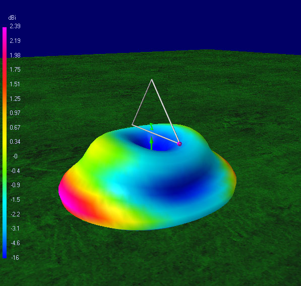
Antenna shown on Fig.3 It is located horizontally to the surface of the earth and has the shape of a square with equal sides.

Fig.3
This antenna is characterized by a low suspension height, which allows it to be used where it is not possible to hang the antennas not vertically or at an angle. The input impedance of the antenna due to the low height of the suspension has different resistance on the bands, which makes it difficult to use it as one antenna in a multi-band version, but for each band the antenna made and matched according to the proposed circuit works great, but it naturally has all the disadvantages of low-mounted antennas .
Closed-circuit wire antennas on HF are widely used by radio amateurs of all countries and nationalities. This is due to their undeniable advantages (which you undoubtedly know once you read this article, and if not, you can easily find them on the Internet). I wanted to tell my story of creating the Delta Loop antenna, because... I encountered some difficulties in building it and I think that my experience may be useful to someone.
Making a Delta Loop antenna with your own hands is not difficult, as one friend said, it will take half an hour with two 15-minute smoke breaks. Let's start by determining the operating ranges and location of the antenna. In my case, a range of 80 m (3.5 MHz) was needed and, accordingly, the perimeter of the antenna should be about 80 m. The suspension was viewed only from the balcony (thanks to the neighbors living on the top floors - radiation and all that) under the balcony there is a one-story building on the roof of which you can attach the two lower corners of the antenna. The triangle did not work as a current triangle, so it would be more correct to call my antenna a “multi-band irregular parallelepiped”.
Well, let's start selecting materials. We will need: 43 meters of field wire (double), two RF connectors (male and female), two ferrite rings 300-500 NN, nylon rope, 2 terminal blocks and finally a solder box. We make a balancing device from the rings, and unwind the vole into 2 coils of single wire (Fig. 2
Rice. 1 
Rice. 2
We connect the vole into one long wire (so that it does not get tangled when unwinding) as it is written in how to connect a vole. And we install the balun and the case part of the connector in a solder box as shown in Fig. 3. 
Rice. 3
Well, actually the preparation is completed, now we proceed to the second stage of installing the antenna. We stretch our 86 m (43 m+43 m) voles in such a way that the shape of the entire structure resembles an equilateral triangle as much as possible (I didn’t succeed very well). We stretch this thing using a simple nylon rope (of course, you can use various types of insulators, but I just tied the rope to a vole). Approximate diagram my “stretch” in Fig. 4 
Rice. 4
We fix a junction box with a simulating transformer on the wall of the house at the point where the antenna is powered. Fig. 5. I fed the antenna through one of the upper corners of the parallelepiped. 
Rice. 5
Well, actually now the third stage of setup. We tune the antenna by reducing the overall perimeter of the antenna. I set it up using an x1-47 frequency response meter and a directional coupler (thanks to Volodya “Hoop”). But you can make a simple field strength meter and adjust it according to the maximum induced current on the measuring antenna. The process of such setup is described in the article on how to set up an antenna without complicated measuring instruments. Now let's get back to the setup results. In general, I think it is sufficient to simply provide you with the resulting graphs. See Fig. 6 and Fig. 7. 
Rice. 6 
Rice. 7
This is the design I came up with. I’m happy with the performance of the antenna; I haven’t noticed any differences with the regular-shaped Delta Loop yet (I had one until I had a fight with my neighbors). In general, good luck with your construction and long-distance QSOs.
RK3DBU 73!
9 thoughts on “ Delta Loop (or triangle antenna or simple multi-band antenna or HF Delta Antenna)”
- Yuri,UB6AFC
I’ve been struggling with a similar antenna for almost a year now. Of course, not every day, but if you count, it’s about two months out of the year. I read on the Internet about the excellent results of the Delta 80m band. I struggle with it this way and that, but to achieve the desired SWR, I still can’t. I made it from thick field wire P-268 into one core. The wire is strong, light and relatively cheap. But I initially did not take into account its shortening coefficient! After all, it has a different resistance from copper! And insulation, in my opinion, makes some adjustments. Built an equilateral triangle in the private sector there is one mast -15m. The angle turned out to be approximately 45, as recommended. The cable is 28 meters, RK-50 Podolsky 10mm on the outside, then along the way I cut it to 27m20cm. The field pole from the existing 86m was shortened by 79m50cm. Resonance was received at 3.680 MHz. SWR 1.8 resistance 86 ohms. I built a quarter-wave transformer from a 75 ohm cable 13.90 m long. Resonance 3.730 SWR-1.56 resistance 51 ohms, reactance + 32. And what to do next? I don’t know. They answer, I hear it seems good, according to good passage! Can anyone help? Has anyone already completed this? I would be very grateful. Yuri, UB6AFC/73!!!
- RK3DBU Post author
Greetings UB6AFC!
Many people struggle with their antenna all their lives and don’t get the desired result, so this is a great year :)
For me, the result you described is quite good, SWR 1.8 for a multi-band HF antenna is normal.
As a next step, I would try to replace the quarter-wave transformer with a balun on ferrite rings, I liked this solution better!
Good luck to you! - Kuldybek
It is better to feed a vertical Delta loop antenna from the bottom corner using 1/4 wave two-wire line as EW8AU advises. In this case, it is easier to coordinate with a RK-50 or RK-75 cable of any length. The polarization is vertical, there is also radiation in the horizontal plane. Initially, the antenna must be tuned to the resonance frequency using a line (cable RK-50/75) half a wavelength from Ku. And then just turn on the two-wire line. Find the cable connection point by moving the cable along the two-wire line according to the SWR-minimum. With such coordination, it is very easy to achieve SWR-1. This is easier than using all sorts of transformers or looking for where the R.in is located. antennas under R. power cable. Tested in practice. The antenna works great. Good luck to everyone and 73! BECK. UN7TX.
- Kuldybek
Good afternoon everyone. A simple option for matching a single-band vertical Delta loop antenna was proposed by EW8AU using a two-wire quarter-wave lily. In this case, you do not need to look for where the R.input antenna is located to match the cable resistance. First, you need to tune the antenna to the desired frequency, and then turn on the two-wire line and look for the matching point with the cable by moving the cable along the line. A simple matching method and you can always achieve precise matching of the antenna with the RK-50 or RK-75 cable. Powering the antenna from the bottom corner. No need to fool your head with all sorts of transformers, etc. The height of the antenna mounting does not matter since the matching can be adjusted. Works with vertical polarization, also has a small radiation with horizontal polarization. Tested in practice. Good luck to everyone. 73! BEK.UN7TX
Refers to loop (frame) antennas, as well as squares. The perimeter of the antenna is approximately equal to the wavelength. Applicable on all HF bands. The designs mainly differ in the antenna suspension and the feed point. The efficiency of the antenna directly depends on the area (a circle is ideal, but it is difficult to achieve), so an isosceles triangle would be preferable. However, any antenna shape is acceptable depending on the specific conditions.
On low-frequency ranges, “lazy deltas” are mainly used (i.e. suspended almost horizontally), and on high-frequency ranges, vertical or inclined “deltas” are mainly used. Low-frequency “deltas” operate on multiple ranges due to excitation at harmonics. At the same time, the main radiation of horizontal “deltas” at the “main” lower frequency is directed upward, which is not very favorable for DX. But at higher harmonics the lobes of the diagram are pressed to the ground.
However, the properties of the “delta” are highly dependent on the specific placement and design (especially low-frequency ones), and therefore have many conflicting reviews.
Vertical deltas
The best place to feed the delta for DX is the bottom corner. However, if the antenna is positioned low and angled upward, it is better to feed through the side corners. In this case, there is more radiation with vertical polarization.
Vertical delta compares favorably with dipole and GP. Compared to a dipole, with the same height, a vertical delta has most of the radiation coming at a low angle to the horizon. Compared to “verticals”, deltas are easier to manufacture, because no complex counterweight system is required.

The antenna input impedance depends on the feed point and ranges from 60-300 Ohms. At high input impedance, power is supplied through a matching transformer. Single-band antennas can be powered through a quarter-wave transformer (Q-matching); a quarter-wave section of 75-ohm cable is connected between the antenna and the 50-ohm cable.
Horizontal deltas
In fact, it is a square turned into a triangle. You have to pay for the savings in guy wires with less efficiency, because The antenna area is smaller.
The horizontal (lazy) delta at 80 m is quite popular. It is often installed between multi-storey buildings. At 80 m the radiation pattern is pea-shaped, i.e. the main radiation is directed upward. Such an antenna can be excited at even harmonics, i.e. 40, 20 and 10 m. Moreover, with increasing frequency, the lobes of the radiation pattern are pressed to the ground.
One of the main problems when setting up such an antenna is the choice of the feed point and coordination with the feeder. Most often, a broadband transformer is used as a matching device. However, it should be taken into account that the input impedance of the delta strongly depends on both the power point and the location in space.
On Internet forums, for the formation of radiation with vertical polarization, powering the “delta” to the “lower” (from the ground) corner is mainly discussed

or at a distance of L/4 from the “lower” point B, i.e. near the ground.

In Figures 1 and 2, at points B and D there is a current antinode, at points A and B there is a voltage antinode.
I immediately rejected this antenna solution: the antenna is already installed low, and with such power supply the main radiation occurs near the ground. In addition, the antenna should be powered as shown in Fig. 2 only from the 9th floor - after all, no one has canceled the desirability of placing the cable perpendicular to the antenna, and it would be good if the radio station was located on the 9th floor.
It is known that the highest intensity of electromagnetic radiation is located near the antinode of the current: “the radiation power of a section of antenna wire is proportional to the square of the current in this section,” i.e. The radiation power in each section of the antenna wire is different, the maximum is at the antinode of the current.
For the antenna shown in Fig. 1, the current antinode at point B is at the very bottom, and for the antenna in Fig. 2 it is slightly above the bottom of the antenna, which is not so bad. However, this option is not suitable for low-hanging “delta”.
Based on these considerations, I decided to make an antenna with power supply in the upper part at a distance of L/4 from the top point B (Fig. 3).

In fact, it is an "inverted" antenna, shown in Figure 2.
Figure 3 clearly shows that the current antinodes (points B and D) are located at a higher altitude, which means that the maximum radiation occurs quite far from
ground, which is very important when the height of the antenna is low. In addition, with this configuration, an almost perpendicular cable connection to the antenna surface is facilitated.
With a 10-meter height of suspension of the upper leaf, a good dual-band (40 and 20 m) antenna was obtained, installed at an angle, because it is impossible to make it completely vertical with such a suspension height. The lowest point of the antenna is literally a meter from the ground, but this has virtually no effect on the radiation efficiency.
It should be noted here that the locations of the current and voltage antinodes indicated in Fig. 1-3 are valid for an antenna with a range of 40 m. In the range of 20 m, 2 waves fit into the antenna, there will be 4 antinodes of current and voltage, so you get complex polarization - vertically -horizontal.
The antenna fabric is made of copper wire with a diameter of 2 mm in enamel insulation. The delta is an equilateral triangle with sides of 14.34 m, perimeter - 43.02 m. The distances between points A, B, C and D (Fig. 3) are equal and amount to 10.75 m each. The distance from power supply node B to the upper angle - 3.58 m. With such dimensions, the resonant frequencies of the antenna are 7040 and 14100 kHz, the current antinodes B and D are opposite.
If these proportions are observed, the antenna may have a certain gain in some directions. If necessary, it is convenient to shorten the lower angle, reducing the segment of 3.58 m, for example, to 3.50 m. A slight inaccuracy in the horizontal location of points B and D does not lead to a noticeable deterioration in the performance of the antenna.
We had to abandon the balun at the power point because... it is subject to wind loads. Therefore, at the power point, instead of a heavy balun, 5 RF-130S ferrite “latches” are installed on the cable. For the same reason, we had to abandon any coordination in the power supply unit. The cable shield is connected to the top of the antenna, the center wire is connected to the bottom.
The most current characteristics of the antenna (impedance and SWR) were measured by the AA-ZZOM analyzer using a half-wave repeater made from a coaxial 50-ohm cable 14 m long. In the 7 MHz range, the active input impedance was 120 Ohms, in the 14 MHz range - 140 Ohms . Due to the insufficient height of the suspension, there is a reactive component of the input impedance, therefore, in the 7 MHz range, SWR = 3.0; in the 14 MHz range - 4.0.
In this situation, it was decided to reduce the SWR by using a matching section of 75-ohm cable. By combining the connection of short sections of such cable with a length of 10 cm, 20 cm, 30 cm, 50 cm, 1 m, 2 m, 3 m, 3.5 m equipped with cheap television connectors, after a half-wave repeater it turned out that in the 7 MHz range a cable section with a length of 6 is required .9 m, in the range of 14 MHz - 3.5 m, which made it possible to obtain SWR = 1.2 in the range of 7 MHz; in the 14 MHz range - 1.5.
As a result, it was decided to connect a piece of 75-ohm cable 3.5 m long directly to the antenna, and then a 50-ohm cable 8.6 m long (14.1 m in total). Unfortunately, due to an inaccurate choice of the length of the half-wave repeater (it was determined by calculation), in the 7 MHz range the SWR was 2.0; in the 14 MHz range - 2.3. This is not so bad - with an SWR of up to 3.0, all the power goes to the antenna. Moreover, increased SWR is available only in a cable 14 m long.
The cables have a diameter of 10 mm and a stranded center conductor. A plastic elbow about 15 cm long, cut to the diameter of the cables, is attached to the junction of the cables, which ensures a reliable connection under wind loads.
There is nothing below that prevents the installation of a current balun equipped with connectors, which will finally cut off possible common-mode currents.

In fact, a 7 MHz control system can operate in the ranges from 1.8 to 15 MHz. The 14 MHz control unit uses a coil of copper tube with a diameter of 6 mm (1+2+4+4 turns, 11 turns in total), and it can be used in the ranges of 7-29 MHz.
If instead of the last 4 turns you wind 8 (there will be 15 turns in total), then, in principle, the control system will work starting from 3.5 MHz, and possibly from 1.8 MHz (you should check it practically). Due to the ease of manufacture, I made 3 of these control systems. As a result, after the matching devices, the frequency band without a reactive component was 400 kHz on the 40-meter range and 380 kHz on the 20-meter range.
This coordination was done in order to reduce losses as much as possible in the 50-meter coaxial cable, which is connected to the second antenna switch. There are 20 ferrite “latches” installed in two places on this cable. The SWR in a long cable connected to the output of the matching device is about unity. Matching devices on lumped elements can be easily replaced with additional sections of 75-ohm cable, the lengths of which will have to be selected.
The antenna can be simplified if it operates on one band. In this embodiment, the length of the 75-ohm cable section connected to the antenna fabric is 3.5 m in the 14 MHz range and about 7 m in the 7 MHz range. The matching device can be installed in the radio station premises or without it at all.
There is another option: power the antenna only with a 75-ohm cable (for example, RK75-4-11). This is how it was used in the field with a half-wave repeater (about 28 m) and a 9-band switch. In September 2013, Sergey, RW9UTK, and I worked in the field from the relatively rare RDA area KE-21. The antenna operated on two bands and was installed at a 12-meter height on two fiberglass pipes. The antenna worked perfectly - at some moments we learned what a pile-up was.
There, in the field, the AA-ZZOM analyzer measured some characteristics of the antenna, which, due to the higher suspension, turned out to be noticeably better than that of the antenna installed at a 10-meter height. In the 40m range there was no reactive component at all, Rin = 141 Ohm, SWR = 1.91, band at SWR level = 2.0 - 80 kHz, at SWR level = 3.0 - 300 kHz, active resistance remains in the band 800 ( !) kHz. In the range of 20 m, the reactive component was also absent, Rin = 194 Ohm, SWR = 2.56, SWR level band = 3 - 620 (!) kHz, active resistance remains in the band 630 (!) kHz.
Coordination was carried out using a homemade control system, to which a 75-ohm cable was connected. The use of a matching device made it possible to obtain SWR = 1.0 on both bands in a 50-ohm cable connecting the control system to the transceiver.
A wide operating frequency band without reactance is a remarkable property of closed circuit antennas. There is no need to rebuild the control system within the amateur band; it is enough to configure it at one point. In this case, the control system may be located quite far from the transceiver.
In the field, we used P-274 double field wire as an antenna fabric. This wire in polyethylene insulation has a certain shortening coefficient, so the perimeter of the antenna turned out to be somewhat smaller, despite the higher height of the suspension than at home, and amounted to 42.70 m.
There was also an equilateral triangle with a side of 14.23 m. The distances between points A, B, C and D are also equal and amount to 10.67 m each. The distance from the power supply unit to the upper corner is 3.56 m.
Some problems arose with the balun, which is part of the universal line: plastic circles from the pyramid toy were used to move the antenna sheet, and the balun moved slightly downward from the designed point (3.56 m from the top). Despite this, the antenna worked just fine, because... on 12-meter pipes it was installed almost vertically.
It is planned to move the balun to the beginning of the line, providing it with connectors. to maintain protection against common mode currents. In addition, you can put ferrite “latches” on a cable lying on the grass or pass it through a ferrite ring several times - a cable with a diameter of 7 mm allows this.
It is also planned to test the antenna in field conditions, but at a height of 16 m. Again, fiberglass masts will be used. The antenna will be installed vertically. I will certainly report the results of the test.


